Device for measuring parallel degree, distortion degree and center distance of large and small head holes of connecting rod of piston engine

A piston engine and measuring device technology, which is applied to measuring devices, fixing devices, mechanical equipment, etc., can solve the problems of not being easy to use, expensive and not portable, etc.

Inactive Publication Date: 2011-09-07
CIVIL AVIATION FLIGHT UNIV OF CHINA
View PDF5 Cites 23 Cited by
  • Summary
  • Abstract
  • Description
  • Claims
  • Application Information

AI Technical Summary

Problems solved by technology

The connecting rod comprehensive measuring instrument can only be used for connecting rods with small deformation, and the measurement range is relatively narrow...

Method used


Image

  • Device for measuring parallel degree, distortion degree and center distance of large and small head holes of connecting rod of piston engine
  • Device for measuring parallel degree, distortion degree and center distance of large and small head holes of connecting rod of piston engine
  • Device for measuring parallel degree, distortion degree and center distance of large and small head holes of connecting rod of piston engine

Examples


Embodiment Construction

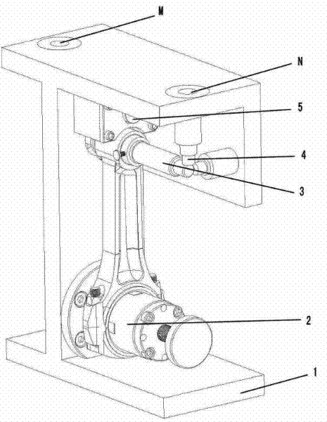
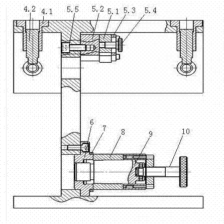
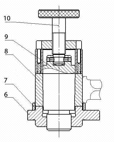
[0027] Such as figure 1 , figure 2 , image 3 , Figure 6 , Figure 7 As shown, the measuring device for parallelism, torsion, and center distance of the connecting rod of the piston engine includes a base 1, a connecting rod positioning mechanism 2, a connecting rod fastening mechanism 5, a measuring shaft 3, and a measuring contact 4; The base 1 has a bottom plate, a vertical vertical plate, a horizontal top plate, and a vertical side plate. The bottom plate, top plate, and vertical plate are combined into an "I" shape, and the side plate and the top plate are combined into an "L" shape. , the facade of the vertical plate, the top surface of the top plate, and the external surface of the side plate are three-dimensional reference planes; the connecting rod positioning mechanism is assembled on the lower part of the vertical plate, and the connecting rod is vertically arranged, and its low hole is sleeved on the positioning mechanism, so that The central axis of the hole...


PUM


Abstract

The invention discloses a device for measuring a parallel degree, a distortion degree and a center distance of large and small head holes of a connecting rod of a piston engine. The device comprises a pedestal, a connecting rod location mechanism, a connecting rod fastening mechanism, a measuring shaft, and measuring contacts; the pedestal is provided with a bottom plate, a vertical upright plate, a horizontal top plate, and a vertical side plate; the bottom plate, the top plate and the upright plate are combined into an I shape; the side plate and the top plate are combined into an L shape; the upright surface of the upright plate, the top surface of the top plate and the facade of the side plate are three-dimensional reference surfaces; the connecting rod location mechanism is mounted on the lower part of the upright plate, and the connecting rod is vertically arranged; a low hole of the connecting rod is sleeved on the location mechanism to make a central axis of the hole vertical to the upright plate; the connecting rod fastening mechanism is mounted on the upper part of the upright plate and corresponds to the high end of the connecting rod to compress and fix the connecting rod on the pedestal; the measuring shaft is mounted in a high hole of the connecting rod and is in close fit with the hole; two pairs of measuring contacts are arranged, wherein one pair of measuring contacts is vertically arranged on the top plate and corresponds to upper edges of the two ends of the measuring shaft; and the other pair of measuring contacts is horizontally arranged on the side plate and corresponds to side edges of the two ends of the measuring shaft. The device has the advantages that: the connecting rod to be measured is precisely located, and the detection data is high in precision and small in error; and the device performs measurement easily and quickly, has strong generality, and can measure connecting rods of engines in various types, specifications and purposes.

Description

technical field [0001] The invention relates to a measuring device for the geometric quantity of a connecting rod of a piston engine, which is mainly used for measuring the parallelism, twisting degree and center distance of the big and small head holes of the connecting rod of the piston engine. Background technique [0002] The connecting rod of a piston engine is an important moving part. One end of it is hinged to the piston, and the other end is hinged to the crankshaft to transmit the output power of the engine to the crankshaft. During the working process of the engine, the connecting rod bears strong alternating loads and impact loads. The ambient temperature is high, and there are extremely high requirements for its strength, geometric size, weight and reliability. As the use time increases, the connecting rod will inevitably be deformed (including bending deformation and twisting deformation), which will cause the parallelism of the connecting rod's big and small h...

Claims


Application Information

Patent Timeline
IPC IPC(8): G01B21/22G01B21/16G01B21/32F16B1/04
Inventor 刘显超吴江陈亮周毅常虎山
Owner CIVIL AVIATION FLIGHT UNIV OF CHINA
Why Eureka
Try Eureka