Method for testing dynamic stiffness of machine tool spindle based on MEMS (micro electro mechanical systems)

A technology for machine tool spindles and testing methods, which is applied in the testing of mechanical components, testing of machine/structural components, and measuring devices. High test accuracy and the effect of improving test accuracy

Inactive Publication Date: 2011-09-07
XIAN RUITE RAPID MFG ENG
View PDF4 Cites 8 Cited by
  • Summary
  • Abstract
  • Description
  • Claims
  • Application Information

AI Technical Summary

Problems solved by technology

For the current design and manufacture of machine tools, the general view is to reduce the vibration impact of machine tools by increasing the stiffness. Therefore, the measurement of dynamic stiffness is very important. However, research on the dynamic stiffness of machine tools at home and abroad is still in its infancy. The measurement of dynamic stiffness is often carried out by experience, and there is no clear criterion for dynamic stiffness, which has the disadvantages of low test accuracy of dynamic stiffness and high measurement cost

Method used


Image

  • Method for testing dynamic stiffness of machine tool spindle based on MEMS (micro electro mechanical systems)

Examples


Embodiment Construction

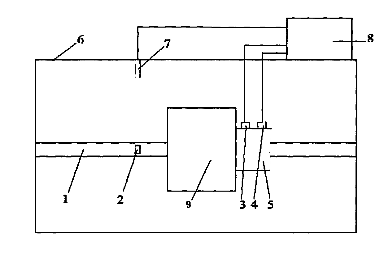
[0014] The present invention will be further described in detail below in conjunction with the accompanying drawings. The present embodiment adopts a grinding machine for testing.

[0015] A method for testing the dynamic stiffness of a machine tool spindle based on MEMS, comprising the following steps:

[0016] In the first step, referring to the accompanying drawings, a force sensor 3 and an acceleration sensor 4 are installed vertically on the shoulder 5 of the machine tool spindle 1, and the normal force signal F(t) of the machine tool spindle and the normal acceleration signal of the machine tool spindle are collected synchronously a(t), paste reflective tape 2 on the machine tool spindle 1 close to the grinding wheel 9, install a photoelectric sensor 7 on the inner wall of the machine tool cabinet 6 close to the reflective tape 2, so that the photoelectric sensor 7 can be irradiated on the reflective tape 2 to collect direction signal, so as to measure the rotational spe...


PUM


Abstract

The invention provides a method for testing dynamic stiffness of a machine tool spindle based on MEMS (micro electro mechanical systems). The method comprises the following steps: firstly, arranging a force sensor and an acceleration transducer on a shaft shoulder of the machine tool spindle along the vertical direction; sticking a reflection belt on the machine tool spindle close to a grinding wheel; arranging a photoelectric sensor on the inner wall of a machine tool cabinet close to the position of the reflection belt; connecting the sensors with an industrial personal computer; and acquiring a normal displacement signal S(t) by utilizing the matrix laboratory (MATLAB) software to perform integration calculation on a signal a(t) for the acquired normal acceleration; acquiring a normal force F(Omega) and displacement S(Omega), by transforming the acquired normal force F(t) and the displacement S(t) into amplitude spectrums by performing the Fourier transform; calculating and acquiring a dynamic stiffness G(Omega) according to the normal force F(Omega) and the displacement S(Omega) by utilizing the following formula: G(Omega) is equal to F(Omega)/ S(Omega); and lastly, judging if the working condition of the machine tool is safe, by comparing the detected dynamic stiffness at different conditions. By using the method, the precision for testing dynamic stiffness is increased. The method provided by the invention has the advantages that the precision for testing dynamic stiffness is high and the testing cost is low.

Description

technical field [0001] The invention relates to the field of testing the dynamic stiffness of a machine tool spindle, in particular to a method for testing the dynamic stiffness of a machine tool spindle based on MEMS. Background technique [0002] MEMS is the abbreviation of micro-electro-mechanical system, which refers to a micro-electromechanical system that integrates micro-sensors, actuators, signal processing and control circuits, interface circuits, communications and power supplies. Its goal is to explore components and systems with new principles and functions through the miniaturization and integration of the system. [0003] The spindle is one of the important components of the machine tool. The quality of the dynamic performance of the spindle directly affects the processing quality of the machine tool to the workpiece and the productivity of the machine tool. The dynamic stiffness of the spindle of the machine tool is the main evaluation index of the dynamic per...

Claims


Application Information

Patent Timeline
Patent Type & Authority Applications(China)
IPC IPC(8): G01M13/00
Inventor 曹军义李桐林京王琇峰
Owner XIAN RUITE RAPID MFG ENG
Why Eureka
Try Eureka