Energy-saving method and device for product aging test

A technology of product testing and aging testing, which is applied in the direction of measuring devices, power supply testing, measuring electricity, etc., can solve the problems of high power consumption, power consumption, huge energy, etc., and achieve the effect of saving energy and improving stability

Active Publication Date: 2014-09-17
东莞市奇立电源有限公司
View PDF5 Cites 0 Cited by
  • Summary
  • Abstract
  • Description
  • Claims
  • Application Information

AI Technical Summary

Problems solved by technology

In the aging process, a large amount of electric energy is consumed in the form of load heat
In the existing product test mode, the output terminals of each test product are loaded with a load resistor for aging loading, that is, each test product is connected in parallel. Due to the excessive load, the power consumption of this circuit form is too large. Facing its huge energy consumption problem

Method used


Image

  • Energy-saving method and device for product aging test
  • Energy-saving method and device for product aging test
  • Energy-saving method and device for product aging test

Examples


Embodiment 1

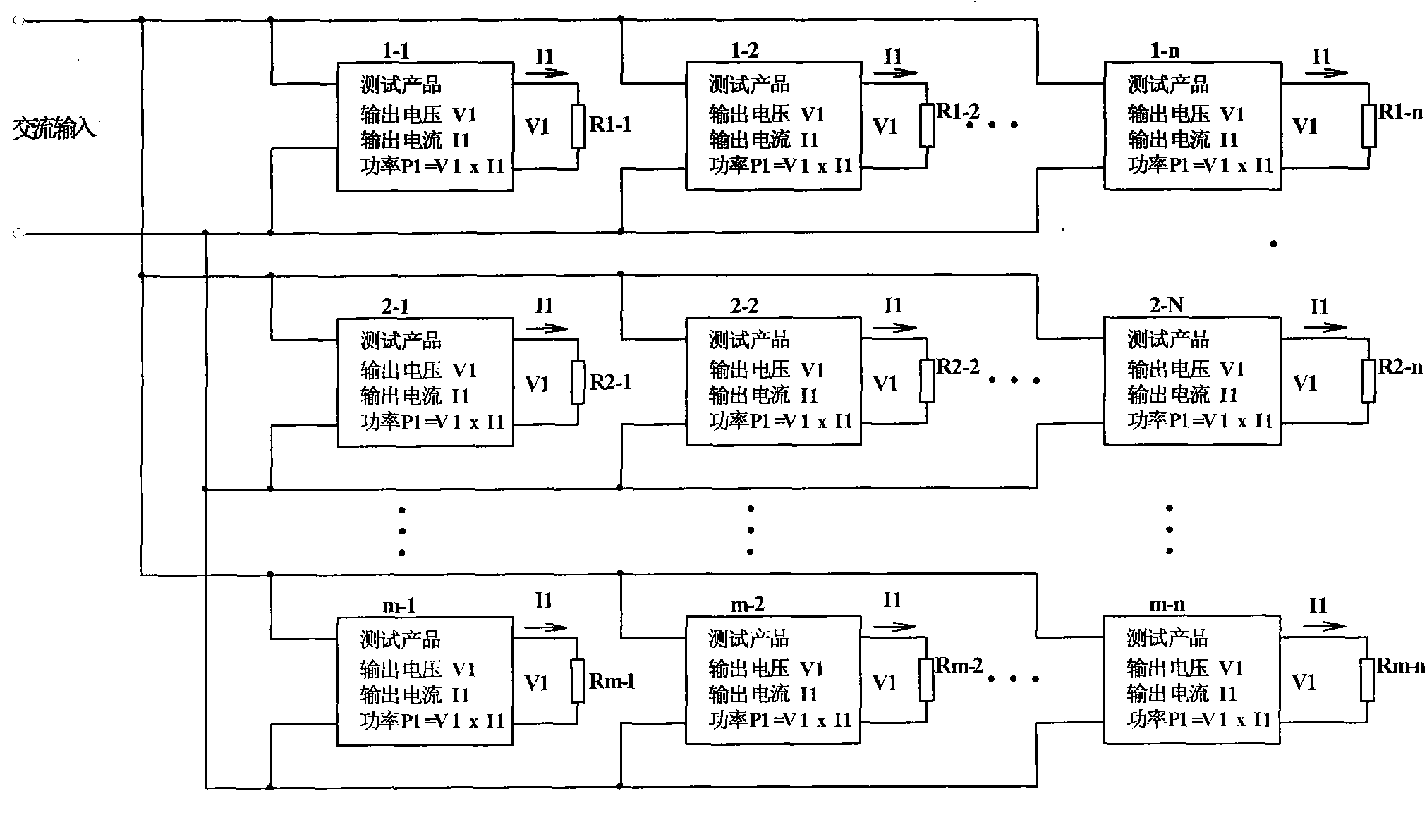
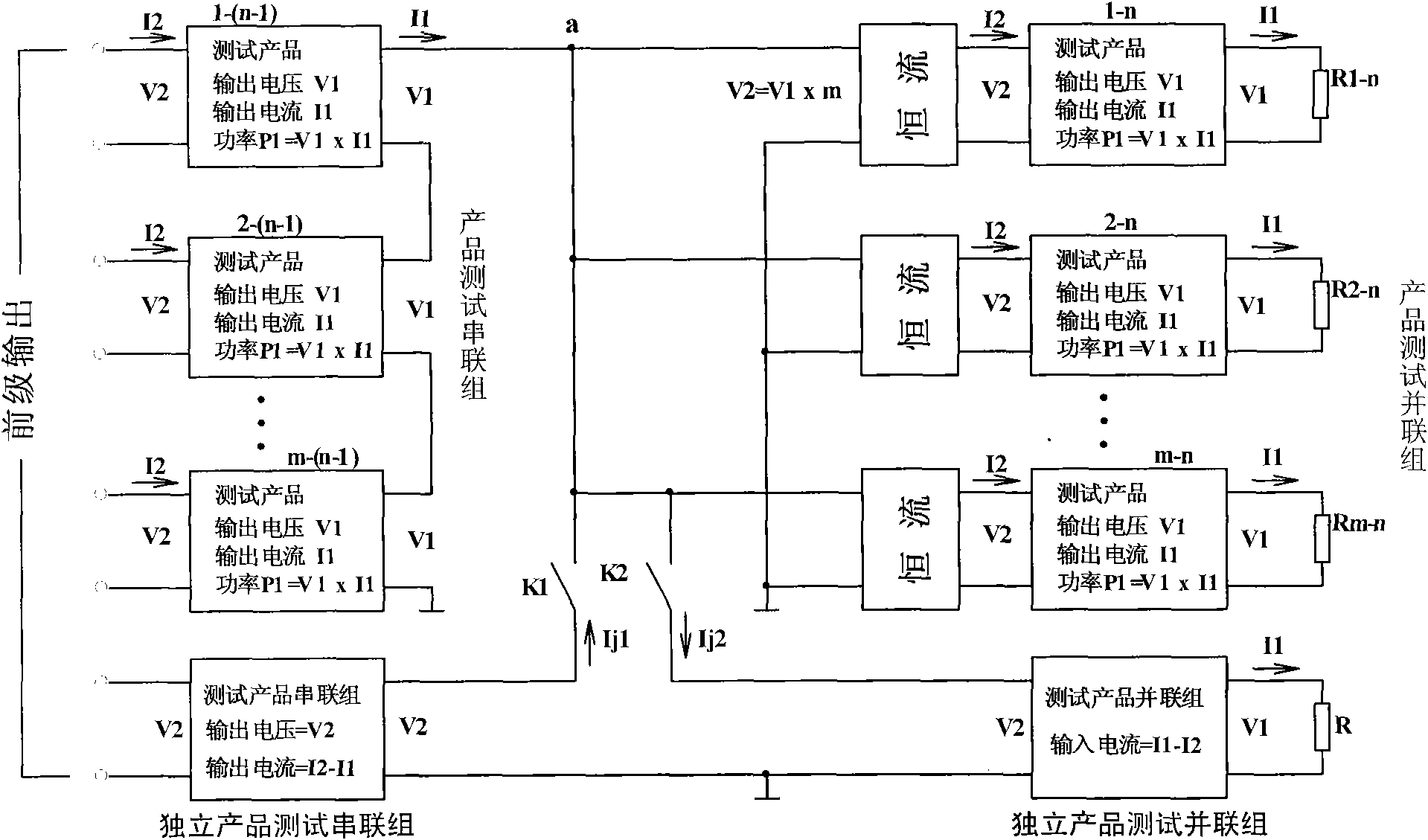
[0032] A product aging test energy-saving method of the present invention, figure 2 The connection diagram of the last two stages is shown. The electrical connection and control principle of the middle stages are the same as those of

[0033] 1) Prepare a plurality of test units 1-1 to m-1 of the same testable product, and connect the output terminals of each test unit in series as the series output terminal a to obtain a group of product test series groups;

[0034] 2) Repeat step 1) multiple times to obtain n-1 groups of product test series groups;

[0035] 3) The electrical connection of the n-1 group product test series group is similar, that is, the input end of each test unit in the latter group is connected to the series output terminal a of the previous group, and each test unit of the rear stage is used as the front stage. load;

[0036] 4) Connect the input terminals of each test unit in the first group to the power supply to provide input voltage V2 and input cur...

Embodiment 2

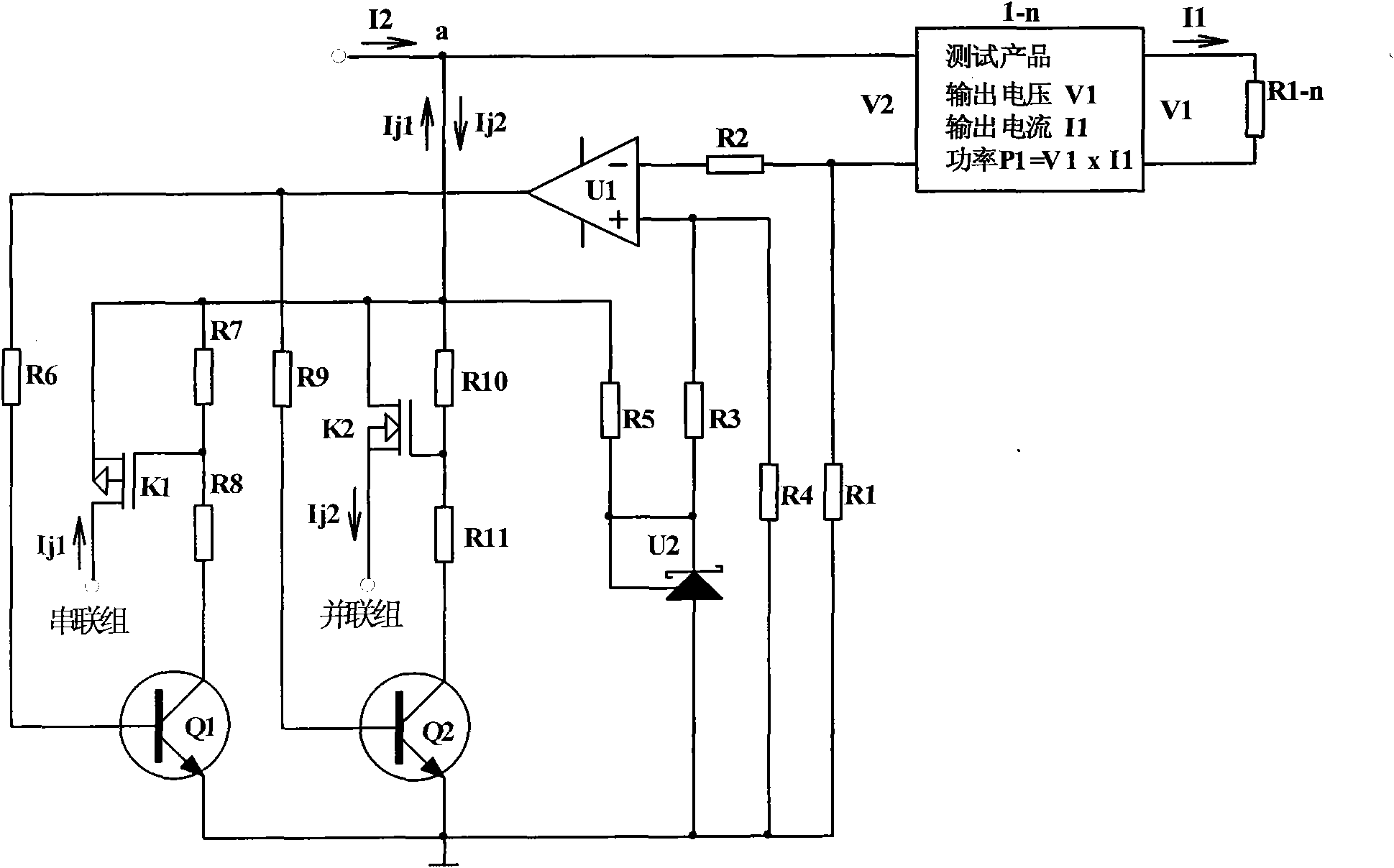
[0056] Such as Figure 4 As shown, when two PNP transistors Q1 and Q2 are used, their emitters are sequentially connected to the series output terminal a of the product test series group through resistors R9, R8, R13 and R12, the collector is grounded, and the compensation current on-off switch K1 uses N Type MOS tube, its drain and source are respectively connected to the series output terminal a of the product test series group and the independent product test series group, the shunt switch K2 uses a P-type MOS tube, and its drain and source are respectively connected to the independent product test The parallel group and the series output terminal a of the product test series group, the gates of the two switches are respectively connected to the series output terminals of the product test series group through resistors R8 and R12.

Embodiment 3

[0058] Such as Figure 5 As shown, when both the compensation current on-off switch K1 and the shunt on-off switch K2 use N-type MOS tubes, the drain and source of K1 are respectively connected to the series output terminal a of the independent product test series group and the product test series group, and the drain of K2 The pole and the source are respectively connected to the series output terminal a of the independent product test parallel group and the product test series group. The gates of the two switches are respectively connected to the series output terminal of the product test series group through resistors R8 and R11. The emitter of the transistor Q1 passes through the resistors in turn R9, R8 and the collector of transistor Q2 are respectively connected to the series output terminal a of the product test series group through R12 and R11, the emitter of Q2 is grounded, the collector of Q1 is grounded and connected to the base through resistor R7.


PUM


Abstract

The invention provides an energy-saving method for a product aging test. A product test parallel group, multiple product test series groups, corresponding independent product test series groups and independent product test parallel groups are included, wherein the front stage of the product test series group supplies power to the later stage; each independent product test series group compensates output current for the front stage; each independent product test parallel group shunts the current for the later stage; and current compensation and shunting are realized by controlling corresponding on-off switches through a constant current unit. The invention also provides a device for implementing the method. By using the method and the device, only a rated load is added at the output of the test product of the last stage, so that a large amount of energy consumption is saved; and by using the constant current unit for controlling the constant input current in test units, the stability of the product test is greatly improved.

Description

technical field [0001] The invention belongs to the field of electronic circuits, and in particular relates to an energy-saving method and a corresponding device for product aging testing. Background technique [0002] When the company leaves the factory and the user inspects the goods, the products such as switching power supplies or chargers it produces need to undergo aging tests. The aging time is divided into 4 hours, 8 hours, 24 hours and other methods. During the aging process, a large amount of electric energy is consumed in the form of heat generated by the load. In the existing product test mode, the output terminals of each test product are loaded with a load resistor for aging loading, that is, the test products are connected in parallel with each other. Due to the excessive load, the power consumption of this circuit form is too large. Facing its huge energy consumption problem. Contents of the invention [0003] The technical problem to be solved by the pre...

Claims


Application Information

Patent Timeline
Patent Type & Authority Patents(China)
IPC IPC(8): G01R31/40G01R31/00
Inventor 申清甫
Owner 东莞市奇立电源有限公司
Why Eureka
Try Eureka