Mechanical safety device for pneumatic hydraulic cylinder driving and stamping equipment

A technology for stamping equipment and safety devices, applied in the field of mechanical safety devices, can solve the problems of uncontrollable swing, limited movement interference, difficult adjustment, etc., to achieve reliable safety protection functions, reduce interference effects, and operate conveniently and quickly.

Active Publication Date: 2011-09-14
苏州托克斯冲压设备有限公司
View PDF5 Cites 2 Cited by
  • Summary
  • Abstract
  • Description
  • Claims
  • Application Information

AI Technical Summary

Problems solved by technology

The length of reciprocating movement of the working piston is different, so that the swing range of the sliding rod with the curved groove is also different, and the swing range cannot be controlled.
[0011] 2. Due to the limited distance from the pressure center line with the working piston rod to the deep throat edge of the body, when the working piston rod travels a long distance, the swing radius of the curved groove sliding rod will inevitably increase accordingly. When the radius size is greater than the throat depth size Movement interference is limited and difficult to adjust
For different working piston rod strokes, only curved groove sliding rods with different radii can be matched to meet the purpose of safety protection
[0013] 4. Since the working piston is often spirally rotated and lifted during the working stroke movement, its torque is greater than the lateral force load of the mechanism of the safety device, which will distort and deform the overall structure of the safety device and affect normal operation
[0014] 5. Whether it is a single-column push block, a double-column push block or a horizontal push block under the mold, the protection is single, and the trouble of changing parts cannot provide comprehensive protection at the same time

Method used


Image

  • Mechanical safety device for pneumatic hydraulic cylinder driving and stamping equipment
  • Mechanical safety device for pneumatic hydraulic cylinder driving and stamping equipment
  • Mechanical safety device for pneumatic hydraulic cylinder driving and stamping equipment

Examples


Embodiment Construction

[0049] The preferred embodiments of the present invention will be described in detail below in conjunction with the accompanying drawings, so that the advantages and features of the present invention can be more easily understood by those skilled in the art, so as to define the protection scope of the present invention more clearly.

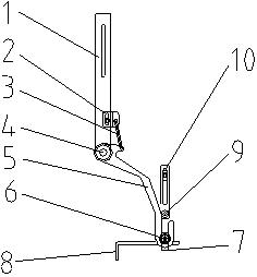
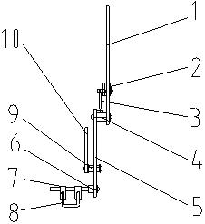
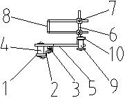
[0050] as attached figure 1 to attach Figure 5 As shown, the stamping equipment in this embodiment includes an equipment body 14, a pressure cylinder 15 fixedly arranged on the equipment body 14, a working piston extension rod 13 arranged in the pressure cylinder 15 movable along the vertical direction, and a working piston extension rod 13 installed in the working cylinder. The upper mold 16 at the lower end of the piston extension rod 13, the lower mold 17 positioned below the upper mold 16, the equipment body 14 is provided with an anti-rotation slide bar 12 that can move in the vertical direction, and the lower end of the anti-rotation slide...


PUM


Abstract

The invention discloses a mechanical safety device for pneumatic hydraulic cylinder driving and stamping equipment. The mechanical safety device comprises a swinging mechanism and a pushing mechanism used for driving the swinging mechanism to swing to and fro; the swinging mechanism comprises an adjustable support plate which is arranged on equipment body, a curved swinging rod of which one end is rotatably connected with the adjustable support plate through a linkage shaft, and a U-shaped block which is arranged at the other end of the curved swinging rod; the adjustable support plate is provided with an adjustable tension spring seat; the adjustable tension spring seat is connected with the curved swinging rod through a tension spring; the pushing mechanism comprises an adjustable roller frame which is arranged on a rotation prevention clamp plate, and a roller which is rotatably arranged at the lower end of the adjustable roller frame; and the roller synchronously drives the curved swinging rod to swing to and fro by taking the linkage shaft as a revolving shaft while a lengthening bar of a working piston is pressed downward or lifted upward.

Description

technical field [0001] The technology relates to a safety device configured for stamping equipment driven by a gas-hydraulic cylinder, in particular to a mechanical safety device for the configuration of stamping equipment used to directly transmit pressure through the working piston rod of the pressure cylinder and act on small workpieces. Background technique [0002] At present, in the category of stamping equipment, it is especially related to a safety protection for the pressure-transmitting stamping equipment through the working piston rod of the pressure cylinder. Because the body of the pressure cylinder working piston rod transmits pressure, the body of the stamping equipment has a simple shape and structure, which is different from the mechanical transmission stamping equipment. In comparison, under the same working pressure conditions, the working range is large and the external volume is small. In particular, small stamping equipment is still the main production ...

Claims


Application Information

Patent Timeline
Patent Type & Authority Applications(China)
IPC IPC(8): B21D55/00
Inventor 张荣魁夏元海
Owner 苏州托克斯冲压设备有限公司
Why Eureka
Try Eureka