Spatial accurate straight-line motion mechanism

A linear motion and precise technology, applied in the direction of manipulators, manufacturing tools, joints, etc., can solve the problems of small motion space and volume, complex processing and manufacturing, and high cost, and achieve the effect of large motion range, convenient manufacturing, and low cost

Inactive Publication Date: 2011-09-14
TIANJIN UNIV
View PDF4 Cites 2 Cited by
  • Summary
  • Abstract
  • Description
  • Claims
  • Application Information

AI Technical Summary

Problems solved by technology

However, most of the existing means of realizing linear motion rely on the constraints of moving pairs, such as slider crank mechanism, cam mechanism, screw pair mechanism, rack and pinion mechanism, etc. The disadvantage of this method is that the processing and manufacturing are complicated and the cost is high.
Although there are also some linear motion mechanisms that rely on connecting rods and rotary joints, most of them are approximate linear motion mechanisms, such as Watt's approximate linear motion mechanisms. also higher
Although it is also possible to use the accurate linear motion mechanism realized by the connecting rod and the rotary joint, there are disadvantages such as the complicated constraint relationship of the mechanism connecting rod, the strict requirements on the size and assembly form of each connecting rod, and the relatively small movement space and volume, so it has not been obtained. practical application

Method used


Image

  • Spatial accurate straight-line motion mechanism
  • Spatial accurate straight-line motion mechanism
  • Spatial accurate straight-line motion mechanism

Examples


Embodiment Construction

[0017] Below in conjunction with specific embodiment, and with reference to accompanying drawing, technology of the present invention is described further:

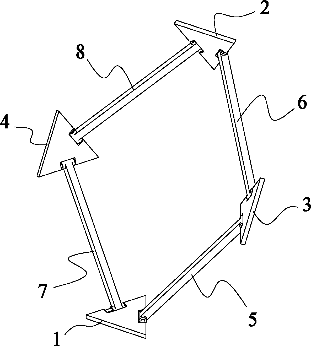
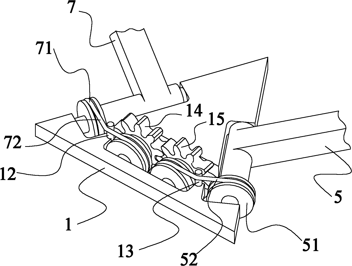
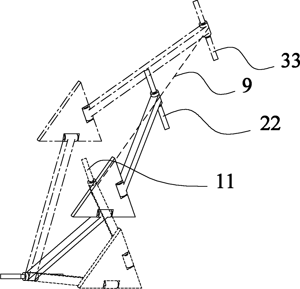
[0018] As shown in the figure, the space-accurate linear motion mechanism of the present invention includes a fixed platform 1 and a mobile platform 2, and it also includes an intermediate platform I3 and an intermediate platform II4. The fixed platform and the intermediate platform II are respectively connected in rotation through a rotary pair The two ends of the left connecting rod I7, the middle platform II and the mobile platform are respectively connected to the two ends of the left connecting rod II8 through the rotation pair, and the described mobile platform and the middle platform I are respectively connected to the right connection through the rotation pair. The two ends of the rod II6, the middle platform I and the fixed platform are respectively connected to the two ends of the right connecting rod I5 through ...


PUM


Abstract

The invention discloses a spatial accurate straight-line motion mechanism, which comprises a fixed platform, a movable platform, an intermediate platform I and an intermediate platform II, wherein the fixed platform and the intermediate platform II are rotationally connected at the two ends of a left connecting rod I through rotation pairs respectively; the intermediate platform II and the movable platform are rotationally connected at the two ends of a left connecting rod II through rotation pairs respectively; the movable platform and the intermediate platform I are rotationally connected at the two ends of a right connecting rod II through rotation pairs respectively; the intermediate platform I and the fixed platform are rotationally connected at the two ends of a right connecting rodI through rotation pairs respectively; rotating shafts are arranged at the same positions of waists of isosceles triangles on all the platforms respectively; both ends of each connecting rod are provided with a sleeve; sleeves at the two ends of each connecting rod are arranged parallel to each other; and the sleeve at each end of each connecting rod is rotationally connected with a rotating shaft arranged corresponding to the sleeve in a sleeved way to form the rotation pairs. The mechanism has a large motion range, can be reversely driven easily and is an accurate straight-line motion mechanism.

Description

technical field [0001] The invention relates to a spatially accurate linear motion mechanism, which can be used as a linear motion joint of a mechanical arm or an operating hand. Background technique [0002] Linear motion mechanisms are widely used in manufacturing equipment, robots, internal combustion engines and other fields. However, most of the existing means to achieve linear motion rely on the constraints of moving pairs, such as slider crank mechanism, cam mechanism, screw mechanism, rack and pinion mechanism, etc. The disadvantage of this method is that the manufacturing is complicated and the cost is high. Although there are also some linear motion mechanisms that rely on connecting rods and rotary joints, most of them are approximate linear motion mechanisms, such as Watt's approximate linear motion mechanisms. Also higher. Although it is also possible to use the accurate linear motion mechanism realized by the connecting rod and the rotary joint, there are dis...

Claims


Application Information

Patent Timeline
Patent Type & Authority Applications(China)
IPC IPC(8): B25J17/00
Inventor 戴建生魏国武王树新李建民
Owner TIANJIN UNIV
Why Eureka
Try Eureka