Charger
A feeder and hopper technology, which is applied in packaging and other directions, can solve the problems of low safety, poor stability and durability, and achieve the effects of ensuring stability, strong practicability, and simple structure
- Summary
- Abstract
- Description
- Claims
- Application Information
AI Technical Summary
Problems solved by technology
Method used
Image


Examples
Embodiment Construction
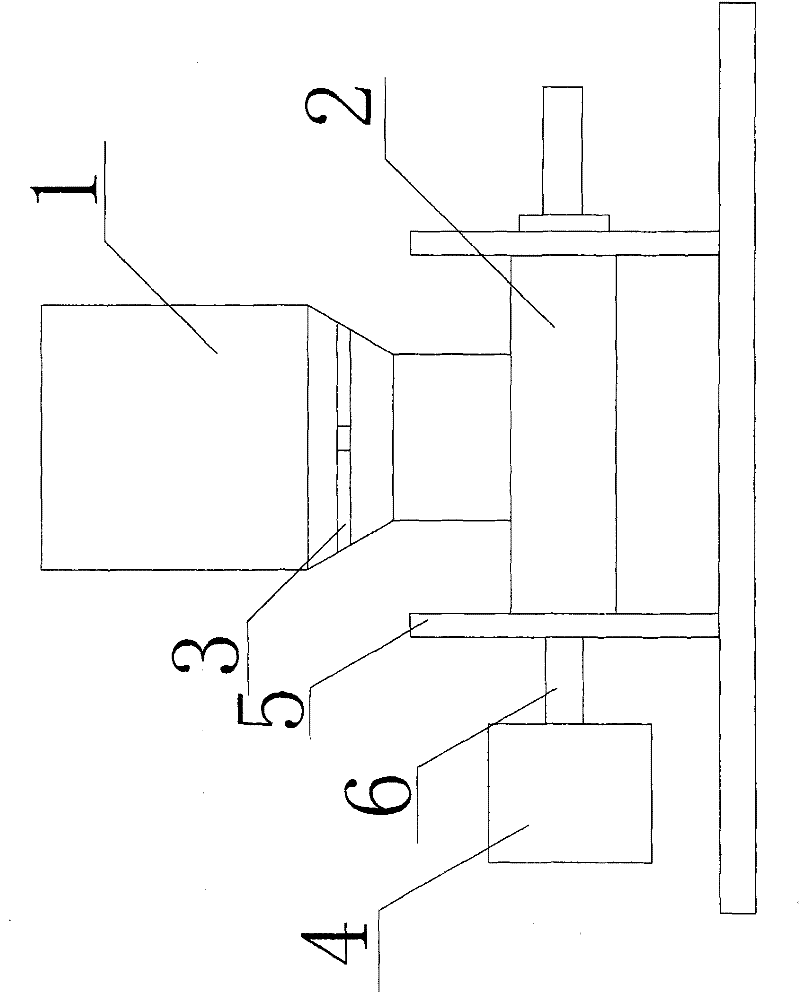
[0011] The present invention is described in further detail now in conjunction with accompanying drawing. These drawings are all simplified schematic diagrams, which only illustrate the basic structure of the present invention in a schematic manner, so they only show the configurations related to the present invention.
[0012] Such as figure 1 It is a structural schematic diagram of the present invention, the feeder includes a hopper 1, a delivery cylinder 2, an impeller 3 and a transmission 4, the hopper 1 is fixedly connected to the delivery cylinder 2, the hopper 1 is provided with an impeller 3, and one side of the delivery cylinder 2 is provided with There is a transmission 4, the delivery cylinder 2 is fixedly connected with the frame 5, and the transmission 4 is fixedly connected with the delivery cylinder 2 through the main shaft jacket 6.
[0013] When in use, the material is added from the hopper 1, and driven by the transmission 4, the conveying cylinder 2 conveys...
PUM
 Abstract
Description
Claims
Application Information
PatSnap Eureka turns technology decisions into work you can execute. Powered by our Innovation Knowledge Graph, it runs expert workflows across engineering, life sciences, materials and intellectual property. Get your review-ready output in minutes.


