Automatic correcting belt conveyor

A tape machine, automatic technology, applied in the directions of sending objects, thin material handling, transportation and packaging, etc., can solve the problems of poor product surface finish, cavity thickness deviation, uneven product edge thickness, etc., to eliminate product thickness unevenness. Effect

Inactive Publication Date: 2011-09-14
LINHAI JINZHENG MACHINERY
View PDF6 Cites 6 Cited by
  • Summary
  • Abstract
  • Description
  • Claims
  • Application Information

AI Technical Summary

Problems solved by technology

[0003] Due to the deviation in the thickness of the working surface and the non-working surface of the diaphragm, there is a deviation in the thickness of the cavity betwe

Method used


Image

  • Automatic correcting belt conveyor
  • Automatic correcting belt conveyor
  • Automatic correcting belt conveyor

Examples


Embodiment Construction

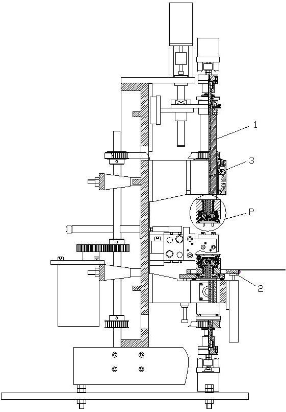
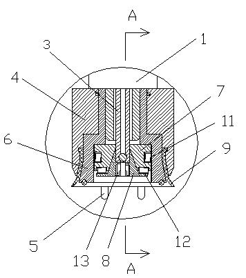
[0021] figure 1 It is a cross-sectional view of the overall structure of the automatic straightening tape machine of the present invention; figure 2 for figure 1 Enlarged view of part P (enlarged view of suction head); image 3 for figure 2 Sectional view along A-A.

[0022] As shown in the figure, the automatic straightening tape machine of the present invention includes a main shaft 1, a workbench 2, and a vacuum pull rod 3 coaxially arranged in the main shaft 1. The lower end of the main shaft 1 and the workbench 2 are respectively provided with a mold for absorbing the lens. The suction head of the upper and lower dies, the suction head includes a suction head jacket 4, a die correction positioning rod 5, a positioning rod limit sleeve 6, a positioning rod locking block 7, a locking block extrusion head 8 and an elastic suction cup 9;

[0023] The locking block extrusion head 8 is fixedly arranged on the lower end of the vacuum pull rod 3, the positioning rod locking...


PUM


Abstract

The invention discloses an automatic correcting belt conveyor, comprising a main shaft, a workbench and a vacuum pull rod, wherein the vacuum pull rod is coaxially arranged in the main shaft, the lower end of the main shaft and the workbench are respectively and correspondingly provided with a suction head used for adsorbing an upper die sheet and a lower die sheet of a lens die, and the suction head comprises a suction head sleeve, a die sheet correcting locating rod, a locating rod limiting sleeve, a locating rod locking block, a locking block extrusion head and an elastic suction disc; andthe locking block extrusion head is fixedly arranged at the lower end of the vacuum pull rod, the locating rod locking block is sleeved outside the locking block extrusion head, the locating rod limiting sleeve is sleeved outside the locating rod locking block, and the suction head sleeve is fixedly sleeved outside the locating rod limiting sleeve. The automatic correcting belt conveyor can be used for automatically correcting the lens die cavity deviation caused by an uneven nonworking plane of the upper die sheet and the lower die sheet of the lens die, and after the lens die cavity deviation is corrected by a die sheet correcting locating rod, the defects, such as nonuniform product thicknesses, poor product smooth finish and the like caused by the uneven thickness of the nonworking plane of the lens die can be eliminated.

Description

technical field [0001] The invention relates to a tape machine, in particular to a tape machine capable of automatically correcting lens molds. Background technique [0002] Tape machine for resin lens molding, the upper suction head is fixed on the main shaft of the tape machine, and the lower suction head is set on the working table of the tape machine. When working, the upper suction head sucks the upper mold of the lens mold, and the lower suction head Suction the upper diaphragm of the lens mold, adjust the position relationship between the upper spindle and the worktable through the automatic control device to adjust the distance between the upper and lower dies, and then use the tape mechanism of the tape machine to stick tape around the die to form a resin lens die. [0003] Due to the deviation in the thickness of the working surface and the non-working surface of the diaphragm, there is a deviation in the thickness of the cavity between the upper and lower diaphrag...

Claims


Application Information

Patent Timeline
IPC IPC(8): B65H37/04
Inventor 潘吕娇
Owner LINHAI JINZHENG MACHINERY
Why Eureka
Try Eureka