Fast wave eliminating/energy dissipating/cushioning device for mining

A buffer device and fast technology, applied in the direction of mining equipment, earthwork drilling, pillars/brackets, etc., can solve problems such as support equipment instability damage, hydraulic buffer damage, high-speed deformation of rock mass, etc., to avoid mechanical production equipment Effect of damage, high compressive strength

Inactive Publication Date: 2011-09-14
LIAONING TECHNICAL UNIVERSITY
View PDF5 Cites 17 Cited by
  • Summary
  • Abstract
  • Description
  • Claims
  • Application Information

AI Technical Summary

Problems solved by technology

However, once there is a sudden rock burst in the mine, the elastic ground pressure energy accumulated in the surrounding rock body will be released instantly in the form of a shock wave, which will have a severe impact on the rigid support body that was originally in a stable state, resulting in damage to the support equipment. Sudden instability and damage, for example, the hydraulic support will cause the hydraulic valve to be washed out due to untimely pressure relief, and the hydraulic support will be crushed to death
[0004] The existing buffers are basically divided into two types: liquid pressure buffering and elastic buffering. The buffering performance and effect are relatively good, but they are not ideal for mine support. The impact ground pressure often releases a large amount of impact energy. Accompanied by the high-speed deformation and failure of the rock mass, this requires the buffer to have the characteristics of fast response, large deformation and strong ability to absorb impact energy, while the elastic buffer converts the impact energy into its own elastic potential energy but cannot release the energy , the hydraulic buffer will be damaged due to insufficient pressure relief in the face of high-speed impact, neither of which can effectively solve the serious problems caused by impact ground pressure

Method used


Image

  • Fast wave eliminating/energy dissipating/cushioning device for mining
  • Fast wave eliminating/energy dissipating/cushioning device for mining
  • Fast wave eliminating/energy dissipating/cushioning device for mining

Examples


Embodiment Construction

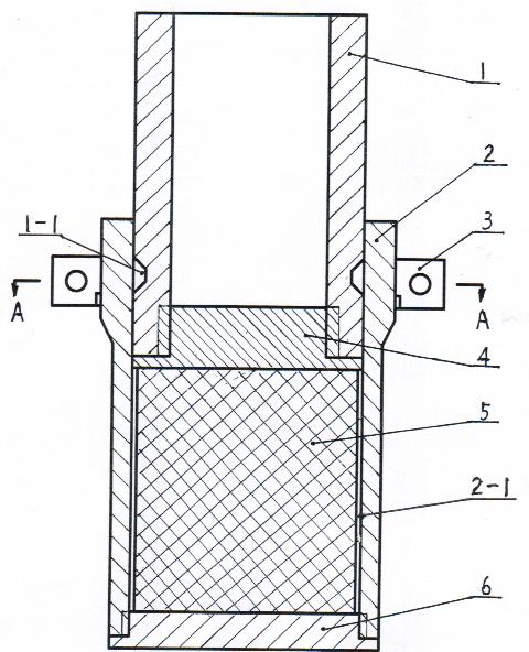
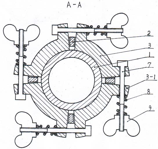
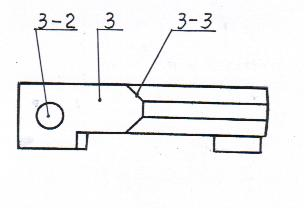
[0015] Examples, see attached Figure 1~3 , the lower rigid sleeve 2 of the mine-used rapid wave dissipation and energy consumption buffer device is a cylinder with a thickened upper wall, the lower part is screwed to fix the external bottom cover 6, and the lower rigid sleeve 2 above the external bottom cover 6 is equipped with a cylinder Shaped plastic energy-absorbing material 5, leaving a gap 2-1 between the energy-absorbing material 5 and the inner wall of the lower rigid sleeve 2. An internal rigid bottom cover 4 is provided on the energy-absorbing material 5, and the internal rigid bottom cover 4 is screwed to fix the upper rigid sleeve 1. The upper rigid sleeve 1 overlaps with the upper thickening of the lower rigid sleeve 2. 1. A trapezoidal groove 1-1 is provided at the overlap between the outer wall and the inner wall of the lower rigid sleeve 2. At the trapezoidal groove 1-1 on the outer wall of the corresponding upper rigid sleeve 1, four pin clips 3 of the same ...


PUM


Abstract

The invention belongs to a support facility for mining security and particularly relates to a fast wave eliminating / energy dissipating / cushioning device for mining. The device comprises an upper rigid sleeve (1) and a lower rigid sleeve (2), wherein the bottom of the lower rigid sleeve (2) is fixed with an external bottom cover (6) through threaded connection, the lower rigid sleeve (2) on the external bottom cover (6) is internally provided with a cylindrical compressible energy absorbing material (5), an internal rigid bottom cover (4) is mounted on the energy absorbing material (5), the upper rigid sleeve (1) is arranged on the internal rigid bottom cover (4) through threaded connection, four pin clamps (3) with the same shape are mounted on the lower rigid sleeve (2) in a clamping manner, the internal surface of a circular ring is provided with a trapezoidal boss (3-3), and the trapezoidal boss (3-3) is embedded in a trapezoidal groove (1-1) in the external wall of the upper rigidsleeve (1). Thus, the fast wave eliminating / energy dissipating / cushioning device for mining can avoid damage of mechanical production facilities and casualty accidents of working personnel to the greatest extent.

Description

technical field [0001] The invention belongs to mine safety supporting equipment, in particular to a mine-used rapid wave and energy consumption buffer device. Background technique [0002] Rock burst is one of the main dynamic disasters in mining engineering. With the increasing mining depth of mineral resources, the occurrence frequency and damage degree of rock burst are becoming more and more intense. , roof fall and collapse, the overall instability of the support structure, the overturning and destruction of mechanical equipment, and even casualties and other accidents have seriously affected the safe mining of mineral resources and the safety of workers. [0003] Commonly used mining support equipment includes wooden supports, steel supports, U-shaped steel supports, single hydraulic props and hydraulic supports, etc., all of which are mainly rigid supports. System security requirements. However, once there is a sudden rock burst in the mine, the elastic ground pres...

Claims


Application Information

Patent Timeline
Patent Type & Authority Applications(China)
IPC IPC(8): E21D15/51
Inventor 潘一山肖永惠李国臻吕祥锋李忠华王爱文
Owner LIAONING TECHNICAL UNIVERSITY
Why Eureka
Try Eureka