Flow control valve special for air spring with additional air chamber

A technology of flow control valve and additional air chamber, which is applied in the field of vehicle air suspension system, can solve the problems such as the correction of the accuracy degree of the inability to adjust the throttle hole, the loss of the function of the additional air chamber, and the loss of adjustment rigidity, so as to achieve precise adjustment and smooth flow. The effect of rapid change of flow area and optimized structure

Inactive Publication Date: 2011-09-14
JIANGSU UNIV
View PDF4 Cites 5 Cited by
  • Summary
  • Abstract
  • Description
  • Claims
  • Application Information

AI Technical Summary

Problems solved by technology

[0003] At present, the commonly used device for controlling the flow area of ​​the throttle tube is the throttle valve, and its defects are: 1. The accuracy of adjustment cannot be corrected according to the damping characteristics of the throttle hole, that is, the pertinence is not strong
2. Ignoring the influence of the air inertia in the pipeline on the performance of the additional air chamber under high-frequency vibration
Specifically, if the diameter of the throttle tube is not large enough, the boundary between the additional air chamber and the main air chamber is clearly defined. When the input signal frequency reaches about 10Hz, the function of the additional air chamber will be completely lost, that is, the ability to adjust the stiffness will be lost.

Method used


Image

  • Flow control valve special for air spring with additional air chamber
  • Flow control valve special for air spring with additional air chamber
  • Flow control valve special for air spring with additional air chamber

Examples


Embodiment Construction

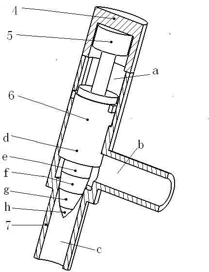
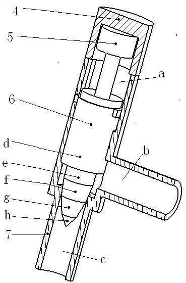
[0011] see figure 1 , the present invention includes a control valve tube body 7, the upper part of the control valve tube body 7 is the control chamber a, the lower part is the pipeline c connected to the additional air chamber, and the side part is another pipeline b connected to the main air chamber, the control chamber a It is coaxial with the pipeline c, and the diameter of the control chamber a is larger than that of the pipeline c, and the control chamber a communicates with the pipelines b and c. The inner diameter of the pipeline b should not be smaller than the inner diameter of the pipeline c, and should not be larger than the inner diameter of the control room a. An upper cover 4 is fixedly installed on the upper end of the control room a, and a stepping motor 5 is arranged in the upper cover 4, and the stepping motor 5 is coaxially connected with the control valve core 6 through an output shaft, and the stepping motor 5 is arranged on the control valve body 7 Th...


PUM


Abstract

The invention discloses a flow control valve special for an air spring with an additional air chamber. The upper part of a pipe body of the control valve is provided with a control chamber a, the lower part of the pipe body of the control valve is provided with a pipeline c which is coaxial with the control chamber a and is connected with the additional air chamber, and the side part of the pipe body of the control valve is coaxially connected with a control valve core; the control valve core is sequentially and continuously provided with a d section, an e section, an f section, a g section and an h section, and the cross sections of the d section and the e section are circular and are respectively in clearance fit with the inner diameter of the control chamber a and the pipeline c; the cross sections of the f section and the g section are round platforms the outer diameter of which decreases sequentially; the cross section of the h section is conical; and the e section, the f section, the g section and the h section extend into the pipeline c to form different through-flow cross section areas, and the stepping control of the through-flow area is realized; when the changes of a damping ratio is dramatic as the changes of the through-flow areas, the flow-through areas change slowly, and the regulation is more accurate; and the change of the damping ratio as the changes of the flow-through areas is slower than the changes of the through-flow areas, and the regulation is more flexible.

Description

technical field [0001] The invention belongs to the field of vehicle air suspension systems, and in particular relates to a flow control valve of an air spring, which is used for semi-active control of the air suspension and adjusts the stiffness and damping of the suspension. Background technique [0002] Semi-active control of a vehicle's air suspension primarily involves controlling the stiffness and damping of the suspension. Under the condition that the flow area controlled by the throttling tube of the air spring remains unchanged, the stiffness can be changed independently by changing the volume of the additional air chamber without affecting the damping value. Under the condition that the volume of the additional air chamber remains constant, the natural frequency and damping will change if the size of the flow area is changed. Therefore, in order to accurately adjust the stiffness and damping of the air spring suspension, the best treatment method is: first adjust ...

Claims


Application Information

Patent Timeline
Patent Type & Authority Applications(China)
IPC IPC(8): F16F9/34
Inventor 江洪王申旭琚龙玉王静李仲兴
Owner JIANGSU UNIV
Why Eureka
Try Eureka