Waste heat evaporator

An evaporator and waste heat technology, applied in the field of waste heat evaporators, can solve the problem of inconvenient cleaning of flue gas pipes, and achieve the effects of facilitating maintenance and cleaning of flue pipes, saving costs, and eliminating cumbersome steps

Inactive Publication Date: 2011-09-14
CHANGZHOU OLYMSPAN THERMAL ENERGY EQUIP
View PDF0 Cites 1 Cited by
  • Summary
  • Abstract
  • Description
  • Claims
  • Application Information

AI Technical Summary

Problems solved by technology

[0003] The technical problem to be solved by the present invention is: in order to solve the technical problem of inconvenient cleaning of the flue gas pipe of the existing waste heat evaporator, the present invention provides a waste heat evaporator whose flue gas pipe is easy to clean

Method used


Image

  • Waste heat evaporator
  • Waste heat evaporator
  • Waste heat evaporator

Examples


Embodiment Construction

[0011] The present invention is described in further detail now in conjunction with accompanying drawing. These drawings are all simplified schematic diagrams, which only illustrate the basic structure of the present invention in a schematic manner, so they only show the configurations related to the present invention.

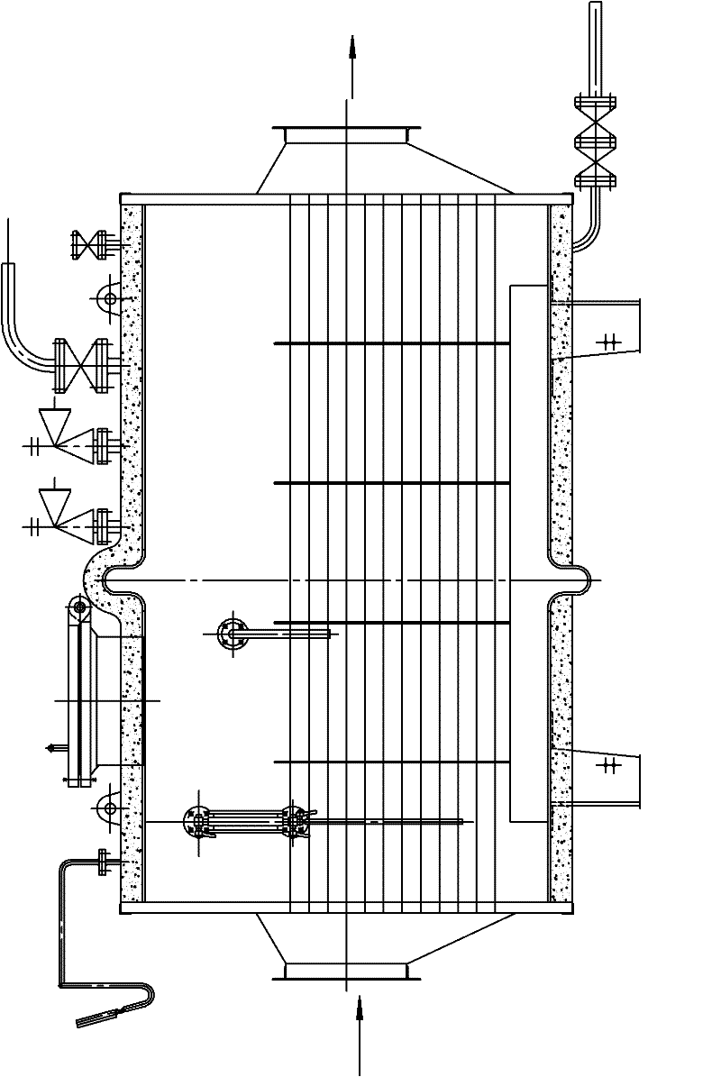
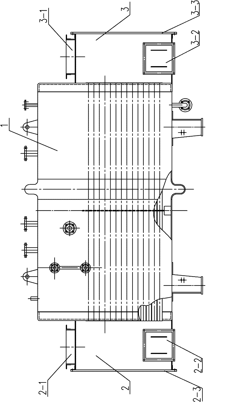
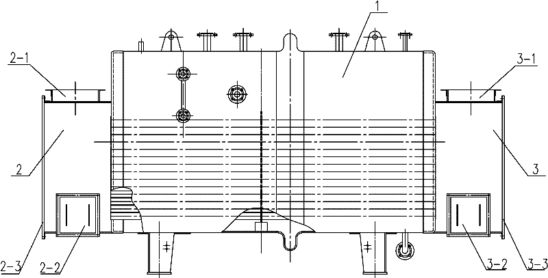
[0012] Such as figure 2 Shown is the optimal embodiment of the waste heat evaporator of the present invention, a waste heat evaporator, including a main engine 1, a flue gas pipe is arranged inside the main machine 1, the air inlet of the flue gas pipe is connected with a flue gas inlet chamber 2, and the flue gas The gas outlet of the gas pipeline is connected with a flue gas outlet chamber 3, the upper end of the flue gas inlet chamber 2 is provided with a flue gas inlet 2-1, and the upper end of the flue gas outlet chamber 3 is provided with a flue gas outlet 3-1, and the flue gas inlet The lower part of the chamber 2 and the flue gas outlet chamber 3 are...


PUM


Abstract

The invention relates to a waste heat evaporator which comprises a main engine, wherein a flue gas pipeline is arranged in the main engine, a flue gas inlet chamber is connected to a gas inlet of the flue gas pipeline, a flue gas outlet chamber is connected to a gas outlet of the flue gas pipeline, a flue gas inlet is arranged at the upper end of the flue gas inlet chamber, a flue gas outlet is arranged at the upper end of the flue gas outlet chamber, and a soot removing opening for inlet gas and a soot removing opening for outlet gas are respectively arranged at the lower parts of the flue gas inlet chamber and the flue gas outlet chamber. As the waste heat evaporator is additionally provided with the flue gas inlet chamber and the flue gas outlet chamber, and both the flue gas inlet chamber and the flue gas outlet chamber are provided with the soot removing openings, soot can be conveniently removed in time; a detachable cover plate is convenient for personnel to maintain and clean a smoke pipe; the complex steps of installing a manhole device are eliminated; and therefore, the cost is greatly saved.

Description

technical field [0001] The invention relates to a waste heat evaporator. Background technique [0002] The waste heat evaporator is an important part of the waste heat boiler. The main structure of the existing waste heat evaporator is as follows: figure 1 As shown, the flue gas inlet and the flue gas outlet cannot be cleaned, and the internal flue pipe cannot be cleaned. In severe cases, the flue gas pipe will be blocked and cause accidents. And it is also extremely inconvenient for future maintenance, and it is necessary to add a manhole device to overhaul, and the operation is complicated to increase the cost. Contents of the invention [0003] The technical problem to be solved by the present invention is: in order to solve the technical problem of inconvenient cleaning of the flue gas pipe of the existing waste heat evaporator, the present invention provides a waste heat evaporator whose flue gas pipe is easy to clean. [0004] The technical solution adopted by the ...

Claims


Application Information

Patent Timeline
Patent Type & Authority Applications(China)
IPC IPC(8): F22B1/18F23J3/02
Inventor 张睿
Owner CHANGZHOU OLYMSPAN THERMAL ENERGY EQUIP
Why Eureka
Try Eureka