Soil body internal horizontal displacement test technology for underground structure vibration table testing

A horizontal displacement and soil technology, applied in the test of the horizontal displacement field inside the soil, in the field of magnetic casing displacement meter, can solve the problems of soil shear deformation and achieve the effect of simple operation and good economy

Inactive Publication Date: 2011-09-14
BEIJING UNIV OF TECH
View PDF3 Cites 9 Cited by
  • Summary
  • Abstract
  • Description
  • Claims
  • Application Information

AI Technical Summary

Problems solved by technology

To overcome the above deficiencies and solve the measurement probl

Method used


Image

  • Soil body internal horizontal displacement test technology for underground structure vibration table testing
  • Soil body internal horizontal displacement test technology for underground structure vibration table testing
  • Soil body internal horizontal displacement test technology for underground structure vibration table testing

Examples


Embodiment 1

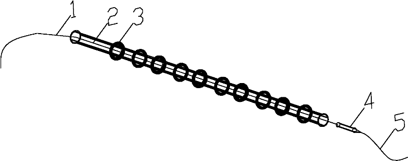
[0021] Implementation 1: Magnetic casing displacement gauge. Select the PVC pipe 2 with an outer diameter of 53 mm and an inner diameter of 48 mm to keep both ends transparent. According to the size of the model box in the shaking table test, the length of the PVC pipe is selected, and the length is required to be greater than the maximum cross-sectional size of the model box; the magnetic cutting ring 3 is Circular, with an inner diameter of 54mm, an outer diameter of 74mm, and a wall thickness of 5mm, set on the outside of the PVC pipe with a spacing of 500mm; the magnetic probe 4 is a cylindrical + conical structure, the top of the magnetic head is connected to a steel wire 5 with a diameter of 1.2mm, and the tail is connected for measurement Soft ruler 6, the measurement accuracy is 0.1mm, the measuring soft ruler is connected to the induction sounder, the overall layout effect diagram is as follows figure 1 shown.

Embodiment 2

[0022] Implementation 2: Test method for the horizontal displacement field inside the soil. In the shaking table test, after the filling soil reaches a certain height, the PVC pipe 2 is passed through one end of the model box 6, the magnetic cutting ring 3 is installed, and then the other end of the model box 6 is passed through to keep the two ends of the PVC pipe 2 open. Permeate, then continue to fill and bury the magnetic ring 3. At this time, the magnetic ring 3 forms a magnetic field inside the PVC pipe 2 and moves together with the soil in the horizontal direction. According to this method, arrays of magnetic casing displacement gauges are arranged on the section of the model box, such as Figure 5 shown. During the measurement, the magnetic probe 4 is pulled by the pull wire 5 and slowly moves from one end of the PVC pipe 2 to the other end. During the moving process of the probe, the magnetic field formed by the magnetic ring 3 must be cut, and the sounder of the r...

Embodiment 3

[0023] Implementation 3: Measurement method of dynamic change of horizontal displacement. After the displacement gauges are all buried, use the process reading method introduced above to record the original position of each magnetic ring. With the development of the shaking table test, the test frequency of the horizontal displacement field of the soil should be increased. In the shaking table test of underground structures, the vibration test is often carried out according to different working conditions, and the vibration will be stopped during each test. The horizontal test of soil displacement can be carried out between working conditions, so that the test frequency is increased, and at the same time Will affect work efficiency. By arranging the test results in chronological order, the dynamic change process of the horizontal displacement inside the soil can be obtained.


PUM


Abstract

The invention provides a soil body internal horizontal displacement test technology for underground structure vibration table testing, and belongs to the technical field of civil engineering. A magnetic bushing displacement meter comprises a polyvinyl chloride (PVC) bushing (2), a magnetic cutting ring (3) and a connecting line type magnetic probe (4), wherein the two ends of the PVC bushing (2) are open; the magnetic cutting ring (3) is a circular magnetic ring which is sleeved outside the PVC bushing (2); the magnetic probe (4) is cylindrical, one end of the magnetic probe (4) is provided with a guy line (5) and the other end of the magnetic probe (4) is connected with a measuring soft ruler (1); and the magnetic probe (4) is freely arranged at one end in the PVC bushing (2). The test technology for a soil body internal horizontal displacement field comprises a soil body horizontal static displacement field measuring technology and a horizontal displacement dynamic change measuring technology. The technology has the characteristics of simple structure, low cost, high reliability and easiness in implementation and maintenance, and is expected to be popularized in other similar tests or tests of an engineering soil body internal horizontal displacement field.

Description

technical field [0001] The invention belongs to the technical field of civil engineering, and relates to a magnetic casing displacement gauge and its testing technology for the horizontal displacement field inside the soil. Background technique [0002] Earthquake disasters in recent years have shown that a large part of the damage to underground structures such as subways is due to overturning and cracking caused by excessive deformation of the foundation, or cracks caused by differential settlement that affect the normal use of engineering structures, that is, large deformation of soil damage to underground structures. From the development of seismic design methods at home and abroad, it can be seen that the guiding ideology of seismic design of underground structures has gradually developed from the traditional strength judgment to the design principle of deformation control (response displacement method), and more and more attention has been paid to the analysis of soil ...

Claims


Application Information

Patent Timeline
IPC IPC(8): G01B7/02G01B5/02G01M7/02
Inventor 陶连金张波王文沛李文博
Owner BEIJING UNIV OF TECH
Why Eureka
Try Eureka