
Liquid-injection type online dynamic balance head structure for high rotating speed

A high-speed, liquid injection technology, applied in the field of dynamic balance, can solve the problems of small liquid injection time window, difficult precise control of intermittent liquid injection, splashing of liquid spray, etc., to reduce difficulty, eliminate the limitation of liquid injection time window, Effects that improve accuracy and balance effects

Inactive Publication Date: 2011-09-14
XI AN JIAOTONG UNIV
View PDF5 Cites 16 Cited by
  • Summary
  • Abstract
  • Description
  • Claims
  • Application Information

AI Technical Summary

Problems solved by technology

[0005] Aiming at the defects or deficiencies in the existing design that the time window for liquid injection is small and intermittent liquid injection is difficult to control accurately, the purpose of the present invention is to provide a liquid injection type online dynamic balancing head structure for high speed. The radial liquid injection method solves the problem of spray liquid splashing at high speed; the 360° continuous liquid injection is realized by adopting the annular groove design, which solves the continuous liquid injection and the precise control of the liquid injection volume under high speed conditions, and realizes high speed conditions. online dynamic balance

Method used


Image

  • Liquid-injection type online dynamic balance head structure for high rotating speed
  • Liquid-injection type online dynamic balance head structure for high rotating speed
  • Liquid-injection type online dynamic balance head structure for high rotating speed

Examples


Embodiment Construction

[0030] The present invention is described in further detail below in conjunction with accompanying drawing:

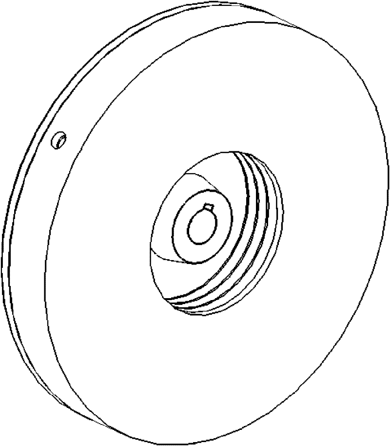
[0031] like figure 1 As shown, it is a structural schematic diagram of a liquid-injection online dynamic balancing head used in the case of high rotational speed according to the present invention.

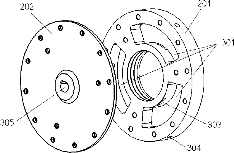
[0032] like figure 2 As shown, the structure of the liquid-injection online dynamic balancing head for high-rotation speed includes two parts: a chassis 202 and a sink plate 201 connected to the chassis 202 . A protruding liquid injection hole 305 is provided at the center of the chassis 202;

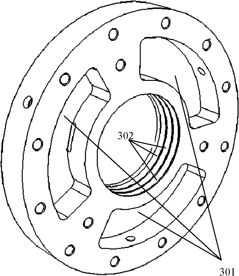
[0033] like image 3 As shown, it is a schematic structural diagram of a sink plate invented for a high-speed liquid-injection online dynamic balancing head structure. The structure of the sink plate 201 includes a central hole as shown in the figure. Three parallel annular grooves 302 are arranged on the inner side of the central hole wall of the sink plate 201. Three uniforml...


PUM

PropertyMeasurementUnit
Sector angleaaaaaaaaaa

Abstract

The invention discloses a liquid-injection type online dynamic balance head structure for high rotating speed, comprising a chassis and a water tank disc connected with the chassis, wherein a liquid injection hole is saliently arranged in the center of the chassis; the water tank disc is provided with a center hole which is sleeved with the liquid injection hole of the chassis; the inner side of the wall of the center hole of the water tank disc is provided with three parallel annular grooves which are circumferentially distributed; the outer side of the center hole of the water tank disc is provided with three sector-shaped liquid storage cavities which are evenly distributed; liquid outlet holes which are communicated with the liquid storage cavities and correspond to the liquid storage cavities are respectively arranged on the annular grooves of the center hole of the water tank disc; and liquid discharge holes are arranged on the outer side walls of the liquid storage cavies. The three liquid storage cavities are respectively of a design structure that the inner side is opened along the radial direction so as to enlarge and balance a liquid injection time window and realize 360-degree continuous liquid injection. The balance head structure is simple, has a low cost, can improve the balancing precision and efficiency through a low-flow continuous liquid injection mode, rectify the unbalance amount of a rotary machine and reduce the mechanical vibration. The invention is suitable for online dynamic balance of a rotor under a high rotating speed condition.

Description

technical field [0001] The invention belongs to the field of dynamic balance, and relates to a structural design of an online dynamic balance head—a liquid-injection type online dynamic balance head structure used in the case of high rotation speed. The online dynamic balancing head structure involved in the invention can continuously inject liquid, realize rapid and precise rotor balance at high speed, and solve the vibration problem caused by unbalanced high-speed rotating body during operation. Background technique [0002] As a key and basic technology of rotary machinery, dynamic balancing technology has been closely watched and valued by industry and academia. A large number of statistical data show that the unbalance of the rotor is usually the main cause of the vibration of the rotary machine. Unbalance will cause the deflection and internal stress of the rotor, aggravate the vibration of the machine, accelerate the wear of parts such as bearings and shaft seals, re...

Claims


Application Information

Patent Timeline
IPC IPC(8): G01M1/30F16F15/36
Inventor 张西宁温广瑞吴婷婷王树典
Owner XI AN JIAOTONG UNIV
Learn More