Coherent radar target echo signal simulating method and device

A coherent radar and target echo technology, which is applied in the field of signal processing, can solve the problems of inability to achieve full coherence, low spectral purity of echo signals, and high spectral purity of radar echo signals, so as to improve detection accuracy and avoid phase noise Effect

Inactive Publication Date: 2011-09-14
中国人民解放军海军航空工程学院青岛分院
View PDF2 Cites 14 Cited by
  • Summary
  • Abstract
  • Description
  • Claims
  • Application Information

AI Technical Summary

Problems solved by technology

[0004] In order to solve the problem that the spectrum purity of the existing radar echo signal is low and full coherence cannot be realized, the present invention provides a full coherent radar target echo signal simulation method, avoiding the use of two or more microwave sources, simulating The radar echo signal has high spectral purity and can achieve full coherence

Method used


Image

  • Coherent radar target echo signal simulating method and device
  • Coherent radar target echo signal simulating method and device
  • Coherent radar target echo signal simulating method and device

Examples


Embodiment 1

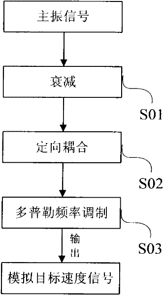
[0030] Embodiment one, such as figure 1 , figure 2 As shown, it is a flow chart of the full coherent radar target echo signal simulation method of this embodiment, including:

[0031] S01, performing attenuation processing on the main vibration signal generated by the radar main control oscillator.

[0032] Specifically, since the power of the main oscillator signal generated by the radar master oscillator is relatively large, in order to facilitate calibration, the signal needs to be attenuated to the power required for calibration.

[0033] S02. Perform directional coupling processing on the attenuated main vibration signal.

[0034] Specifically, the main vibration signal is a high-frequency signal, and in order to ensure unidirectional signal transmission, the main vibration signal needs to be directional coupled to obtain a directional coupled carrier frequency signal.

[0035] S03. Perform Doppler modulation on the carrier frequency signal.

[0036] Specifically, in...

Embodiment 2

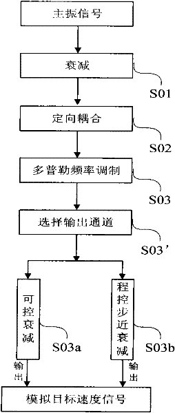
[0050] Embodiment 2 is another embodiment of the full coherent radar target echo signal simulation method of the present invention, see image 3 As shown, Embodiment 1 of the full coherent radar echo signal simulation method based on the present invention includes steps S01 to S07, the difference of which is:

[0051] Step S03' is also included after step S03, selecting an output channel.

[0052] Specifically, after selecting the output channel S03', it includes step S03a and step S03b. The step S03a is the controllable attenuation output, and the step S03b is the program-controlled step attenuation output. By setting two different attenuation output channels, the signal output More flexibility, according to different attenuation needs to choose the appropriate

[0053] The attenuation channel enhances the applicability of the method.

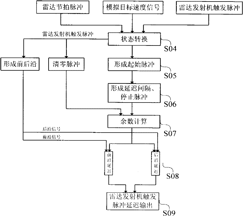
[0054] In step S04, it also includes performing a state transition on the radar tick pulse. The radar tick pulse is a clean timing pulse sy...


PUM


Abstract

The invention discloses a coherent radar target echo signal simulating method. The method comprises the following steps of: attenuating and directionally coupling a dominant oscillation signal sequentially and performing Doppler frequency modulation to obtain a simulative target speed signal; performing state conversion between a trigger pulse of a radar emitter and the simulative target speed signal and processing a conversion result into an initial pulse; processing another trigger pulse, which is subjected to the state conversion, of the radar emitter into a resetting pulse; processing theinitial pulse to form a delay interval and a stop pulse; and performing a remainder computation on the delay interval, the stop pulse and the resetting pulse and outputting the delay interval, the stop pulse and the resetting pulse in a delayed way. The invention also discloses a coherent radar target echo signal simulating device. The coherent radar target echo signal simulating device realizes the attenuation, coupling and Doppler frequency modulation of the dominant oscillation signal and a simulative coherent radar target echo signal is obtained in the absent of a microwave source; the circuit of the device is simple; the target distance parameter simulating scope is large; and the precision is high.

Description

technical field [0001] The invention belongs to the technical field of signal processing, and in particular relates to a method for simulating a full coherent radar target echo signal. Background technique [0002] When testing technical parameters such as the sensitivity of the radar receiver, angle tracking characteristics, missile guidance command channel, and receiver Doppler frequency coverage, microwave sources are required to generate fully coherent radar echo signals in the radio frequency band. The wave method is mainly realized by using the trigger pulse of the radar to control the microwave signal source or another microwave source and superimposing the rated Doppler frequency shift. Since there are at least two microwave sources, the stability of all microwave sources in the radio frequency band is relatively high. Poor, and the spectral purity is low, and there is always phase noise. In this case, PD radar will generate false targets for moving target detection ...

Claims


Application Information

Patent Timeline
Patent Type & Authority Applications(China)
IPC IPC(8): G01S7/40
Inventor 李淑华戚甫锋王勇王守权叶灵伟
Owner 中国人民解放军海军航空工程学院青岛分院
Why Eureka
Try Eureka