
Temperature control timer prepared from time-base circuit

A technology of temperature control and timing circuit, which is applied in the direction of using electric means for temperature control, auxiliary controller with auxiliary heating device, etc., can solve the problems of high brooding cost, high labor intensity, and difficult to control the temperature of the incubator.

Inactive Publication Date: 2011-09-14
刘家发
View PDF2 Cites 13 Cited by
  • Summary
  • Abstract
  • Description
  • Claims
  • Application Information

AI Technical Summary

Problems solved by technology

They generally have outstanding problems such as difficult control of the temperature in the incubator, low hatching rate, high brooding cost, and high labor intensity.

Method used


Image

  • Temperature control timer prepared from time-base circuit
  • Temperature control timer prepared from time-base circuit

Examples


Embodiment Construction

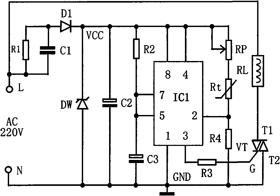
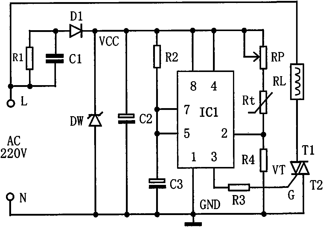
[0014] The present invention can be realized in accordance with the working principle diagram of the temperature control timer made with the time base circuit shown in the accompanying drawings, the description of the accompanying drawings and the technical requirements of the components described below, and in combination with the following embodiments.

[0015] Selection of components and their technical parameters

[0016] IC1 is the time base circuit, the model is: NE555; the time base circuit IC1 is an 8-pin DIP package; the functions of each pin: 1 pin is the negative pole of the DC power supply, 2 pins are the trigger terminal, 3 pins are the output terminal, and 4 pins are the reset terminal. Pin 5 is the control voltage, pin 6 is the threshold (threshold), pin 7 is the discharge terminal, and pin 8 is the positive pole of the DC power supply;

[0017] Rt is a temperature-sensing probe. In this embodiment, a MF12 or MF53 thermistor with a negative temperature coefficie...


PUM


Abstract

The invention relates to a temperature control timer prepared from a time-base circuit, and the timer provided by the invention comprises a mains alternating current (AC), an RC (resistance-capacitance) step-down circuit, a 12V DC (direct current) voltage-stabilized source, a temperature sensitive probe circuit, a timing circuit, a bidirectional thyristor triggering and controlling circuit and a control circuit, wherein the timing circuit consists of a 555-time-base integrated circuit 1 (IC1). In the invention, an automatic temperature control timer is composed of a 555-time-base circuit and a few peripheral components, and through additionally arranging a timing control circuit, the temperature control timer can cut off a power supply for electrical heating timely when a temperature sensitive probe and the control circuit are out of control, thereby avoiding causing greater harms. The temperature control timer disclosed by the invention can be applied to the operations such as industrial production and rural electric heating control, and the like. The temperature control timer disclosed by the invention can be used as an upgrading and updating device for the temperature control of brooding boxes by using an indigenous method of peasant households, and can be used as an independent product so as to carry out development.

Description

technical field [0001] The invention belongs to the technical field of electronic control, and relates to a temperature control timer made of a time base circuit, which is suitable for rural poultry hatching, edible fungus strain cultivation or industrial laboratories. Background technique [0002] At present, some rural poultry hatches with good conditions have switched to electric blankets as heating devices. They generally have outstanding problems such as difficult temperature control in the incubator, low hatching rate, high brooding cost, and high labor intensity. Therefore, along with the problem of electricity consumption in rural areas is generally solved, it is necessary to develop a device for automatically controlling the heating temperature with simple circuit structure, reliable performance, low manufacturing cost, and easy installation and use. The temperature controller of the present invention can be widely used in poultry incubation, edible fungus strain c...

Claims


Application Information

Patent Timeline
Patent Type & Authority Applications(China)
IPC IPC(8): G05D23/30
Inventor 刘家发
Owner 刘家发
Learn More