
Method for constructing distributed dynamic power flow computing system for energy management of electric power system

A dynamic power flow and energy management technology, applied in computing, electrical digital data processing, electrical components, etc., can solve problems such as complex network environments and difficulties in how adjacent subsystems exchange boundary information, and achieve the effect of solving startup problems

Inactive Publication Date: 2013-05-01
NORTH CHINA ELECTRIC POWER UNIV (BAODING)
View PDF3 Cites 0 Cited by
  • Summary
  • Abstract
  • Description
  • Claims
  • Application Information

AI Technical Summary

Problems solved by technology

For example, in reality, each subsystem is independent of each other. Different subsystems are modeled at the connection line, and the modeling methods are different. How to exchange boundary information between adjacent subsystems is very difficult, and the actual network environment Complex, how to deal with various network interference also needs to be carefully considered

Method used


Image

  • Method for constructing distributed dynamic power flow computing system for energy management of electric power system
  • Method for constructing distributed dynamic power flow computing system for energy management of electric power system
  • Method for constructing distributed dynamic power flow computing system for energy management of electric power system

Examples


Embodiment

[0055] Take the standard IEEE-118 node system as an example (such as Figure 5 Modeling of the coordination layer shown), with branches (15-33), (19-34), (30-38), (23-24), (70-74), (70-75), ( 75-69), (77-69), (68-81) are tie lines to divide this system into three independent subsystems S 1 , S 2 , S 3 , respectively as Figure 6 , Figure 7 , Figure 8 mistake! Reference source not found. shown. The modeling steps of the coordination layer are as follows:

[0056] 1) Coordination layer initialization. Read the connection line information, and number the connection line endpoints, and the formed coordination layer node numbers are shown in Table 1. Advertises an object with a naming service.

[0057] 2) Subsystems 1, 2, and 3 respectively resolve the object reference of the coordination layer announcement object from the naming service, and invoke the operation of the object reference to obtain the mapping relationship in Table 1. Then form the corresponding relatio...


PUM


Abstract

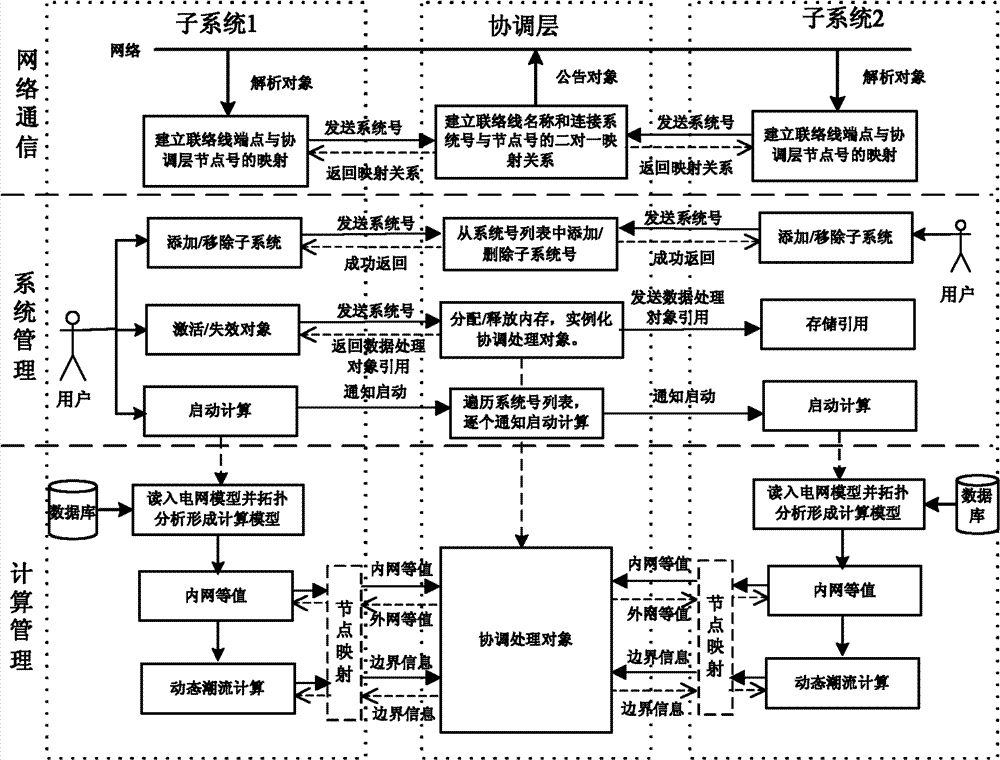
The invention discloses a method for constructing a distributed dynamic power flow computing system for energy management of an electric power system, belonging to the technical field of energy management of electric power systems. The method comprises the following steps of: setting a distributed computing coordination layer in a superior scheduling center, and setting a distributed computing subsystem in an inferior scheduling center. The system comprises three modules, i.e., a network communication module, a system management module and a computing management module, wherein the network communication module is realized by adopting a relatively mature CORBA (Common Object Request Broker Architecture) technology in the distributed field and meets the requirement of a coordinating layer and a subsystem on data exchange; the free entrance or exit of a subsystem is realized by the system management module; the subsystem can be used for controlling the allocation and the release of the internal memory of the coordination layer to solve the problem of starting of power flow computation; and the computing management module is used for realizing procedure management of power flow computation and solving the problem of transmission of link line boundary information during data exchange by forming a node mapping table of a link line local node number and a coordination layer node number. The method meets the requirement of practicability.

Description

technical field [0001] The invention belongs to the technical field of power system energy management, in particular to a construction method of a distributed dynamic power flow calculation system for power system energy management. Background technique [0002] With the development of the power system, regional power grids are interconnected to form a larger-scale system. It is impossible for only one control center to centrally monitor and manage the power grid. my country currently implements a hierarchical and partitioned power grid management model. The entire power grid is based on voltage Levels and regions are managed by national survey, network survey, provincial survey and local survey respectively. The power grids in each region are relatively independent and have their own relatively independent dispatch centers. Power system model, but each subnet does not know the operating parameters and status of other subnets. However, from the perspective of physical structu...

Claims


Application Information

Patent Timeline
Patent Type & Authority Patents(China)
IPC IPC(8): H02J3/00H02J13/00G06F19/00
Inventor 张海波蒋良敏
Owner NORTH CHINA ELECTRIC POWER UNIV (BAODING)
Learn More