Curing of a lens by
ultraviolet light tends to present certain problems that must be overcome to produce a viable lens.
Such problems include yellowing of the lens,
cracking of the lens or mold, optical distortions in the lens, and premature release of the lens from the mold.
In addition, many of the useful UV-curable lens forming compositions exhibit certain characteristics which increase the difficulty of a lens curing process.
For example, due to the relatively rapid nature of
ultraviolet light initiated reactions, it is a challenge to provide a composition which is UV curable to form an eyeglass lens.
Excessive exothermic heat tends to cause defects in the cured lens.
While reducing the level of
photoinitiator addresses some problems, it may also cause others.
For instance, lowered levels of photoinitiator may cause the material in regions near an edge of the lens and
proximate a
gasket wall in a mold cavity to incompletely cure due to the presence of
oxygen in these regions (
oxygen is believed to inhibit curing of many lens forming compositions or materials).
Uncured lens forming composition tends to result in lenses with "wet" edges covered by sticky uncured lens forming composition.
Furthermore, uncured lens forming composition may migrate to and contaminate the optical surfaces of the lens upon demolding.
The contaminated lens is then often unusable.
The low photoinitiator levels utilized in many ultraviolet curable lens forming compositions may produce a lens which, while fully-cured as measured by percentage of remaining double bonds, may not possess sufficient crosslink density on the lens surface to provide desirable
dye absorption characteristics during the tinting process.
An undesirable effect of this method, however, is that the lens tends to yellow as a result of such
exposure.
This method generally requires long
exposure times and often the
infrared radiation absorbed by the lens mold
assembly will cause premature release of the lens from a mold member.
This method, however, is also associated with a higher rate of premature release.
Thicker lenses tend to be more difficult to cure with continuous non-pulsed light.
When
casting a lens, particularly a positive lens that is thick in the center,
cracking may be a problem.
During the process, a large
temperature gradient may build up and the resulting stress may cause the lens to crack.
Once patterns leading to optical distortions form they are difficult to eliminate.
When gelation occurs there typically is a rapid temperature rise.
If the heat exchange with the surroundings is not sufficient enough there will be a runaway situation that leads to premature release, the appearance of thermally caused striations and even breakage.
Premature release of the lens from the mold will result in an incompletely cured lens and the production of lens defects.
Excess liquid that is not removed could spill over the face of the back mold member 90 and cause
optical distortion in the finished lens.
High absorptivity of a photoinitiator in this range, however, is not desirable, especially when
casting a thick lens.
The remaining light will produce a much lower rate of
polymerization below this depth and will result in a lens that has visible distortions.
Although such lenses actually absorb very little visible light, they are cosmetically undesirable.
Photoinitiators are often very
system specific so that photoinitiators that are efficient in one
system may function poorly in another.
A concentration of initiator that is too high tends to lead to
cracking and yellowing of the lens.
Concentrations of initiator that are too low tend to lead to incomplete
polymerization and a soft material.
Sharp intensity gradients through the lens may lead to defects in the finished lens.
In addition, the yellowing tends to disappear if the lens is subjected to the above-described post-cure heat treatment.
Moreover, if not post-cured the yellowing tends to disappear at ambient temperature after approximately 2 months.
If too much TTEGDA is included in the most preferred composition, i.e. greater than about 25% by weight, however, the finished lens may be prone to cracking and may be too flexible as this material softens at temperatures above 40NC.
If TTEGDA is excluded altogether, the finished lens may to be brittle.
TMPTA also contributes to high shrinkage during polymerization.
The inclusion of too much of this material in the most preferred composition may make the finished lens too brittle.
The fully exposed region of the lens will tend to be harder, and the lens may have stresses because of this.
This effect has been observed and may cause premature release or induce cracking.
Mold defects at the edges interfere with the sealing conditions and frequently induce premature release.
It is believed that as the reaction proceeds, the heat generated tends to reduce the adhesion between the shrinking lens and the mold face.
This reduction in adhesion tends to cause the lens to pull away from the mold.
In high curvature (i.e. high power) lenses this problem tends to be even more pronounced because of two factors: (1) these lenses have more thickness and thus more material that is generating heat (which thus speeds up the reaction and generates more heat), and (2) these lenses have a greater thickness differential between the thick and thin portions of the lens, which tends to cause stress on the molds due to differential shrinkage.
It is also possible that the temperatures generated relatively deep inside a thick lens may cause some
vaporization of the
monomer.
Low diopter lenses may be prepared in this fashion, but higher plus or minus diopter lenses may fail.
These lower temperatures tend to permit an increase in photoinitiator concentration, which in turn may speed up the reaction and lower
curing time.
The thickness of the glass molds used to cast polymerized lenses may affect the lenses produced.
In certain applications, all of the lens forming composition may fail to completely cure by
exposure to ultraviolet rays when forming the lens.
Since
oxygen tends to inhibit the photocuring process, portions of the lens forming composition
proximate the
gasket tend to remain uncured as the lens is formed.
Uncured lens forming composition
proximate the
gasket is a problem for several reasons.
First, the
liquid lens forming composition leaves the edges of the cured lens in a somewhat sticky state, which makes the lenses more difficult to
handle.
Second, the
liquid lens forming composition is somewhat difficult to completely remove from the surface of the lens.
Third,
liquid lens forming composition may flow and at least partially coat the surface of lenses when such lenses are removed from the molds.
This
coating is difficult to remove and makes application of scratch resistant coatings or tinting dyes more difficult.
This coating tends to interfere with the interaction of scratch resistant coatings and tinting dyes with the cured lens surface.
As a result of the above problems, often lenses must be tediously cleaned or recast when liquid lens forming composition remains after the lens is formed in an initial cure process.
Doing so, however, tends to create other problems.
Specifically, increased photoinitiator levels tend to cause exothermic heat to be released at a relatively
high rate during the reaction of the composition.
Premature release and / or lens cracking tends to result.
Separating the molds from the cured lens may cause uncured liquids to at least partially coat the lens faces.
This coating occurs because uncured liquid lens forming composition tends to get swept over the faces when the molds are separated from the lens.
It is believed that curing of the lens tends to create a vacuum between the lens and the mold.
If the
oxygen barrier is too thick, then it may not be readily stretchable and / or conformable, and it may not allow a sufficient amount of light to pass through it.
A surfactant has been conventionally employed for this purpose, however surfactants tend to affect the volatility and flow characteristics of lens coatings in an unfavorable manner.
1. The air flowrate on each side of the lens mold
assembly was estimated to be about 18-20 cubic feet per minute.
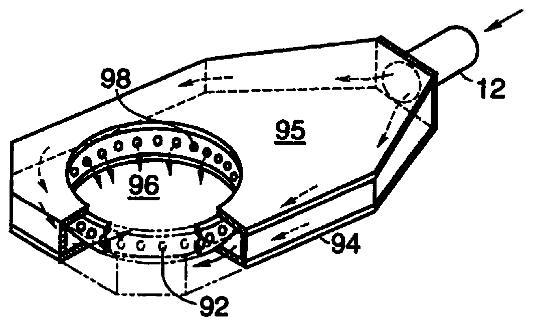
2. The apparatus was modified in that air flowed to and from the openings 96 and orifices 98 (which were themselves substantially unchanged) through a duct behind the lens forming chamber, instead of through pipes (e.g.
pipe 12 in FIG. 5). Essentially plenum portion 95 was expanded so that the walls of the chamber are the walls of the plenum portion 95. FIG. 14 depicts a front view of this lens curing apparatus 800. Air in apparatus 800 flows from the orifices 98, over the lens mold
assembly 802, through ducts 804, through fan 806, through
heat exchanger 808, and then through ducts 810 and back to orifices 98 via air return conduits 824 (shown on FIG. 15). FIG. 14 also shows a
water chiller 812 which cools water and then sends it through conduits 814 and through
heat exchanger 808. FIG. 14 also shows lights 816 and
frosted glass 818. The chamber 820 surrounding lights 816 is not connected to the chamber 822 around the mold assembly 802. In this manner chilled air from orifices 98 does not contact and cool the lights 816 (such cooling tends to cause excessive changes in light output). The chamber 820 is cooled by fans (not shown) which turn on and off depending on the temperature of the surface of the lights 816. FIG. 15 shows a side view of apparatus 800.
3. The air flowrate in and out of the chamber surrounding the lights was varied in accordance with the surface temperature of lights. The air flowrate was varied in an effort to keep the temperature on the surface of one of the lights between 104.5.degree. F. and 105.degree. F.
4. The
ultraviolet light output was controlled to a
set point by varying the power sent to the lights as the output of the lights varied.
5.
Frosted glass was placed between the lights and the filters used to vary the intensity of the
ultraviolet light across the face of the molds. Preferably the glass was frosted on both sides. The
frosted glass acts as a diffuser between the lights and these filters. This
frosted glass tended to yield better results if it was placed at least about 2 nm from the filter, more preferably about 10-15 nm, more preferably still about 12 nm, from the filter.
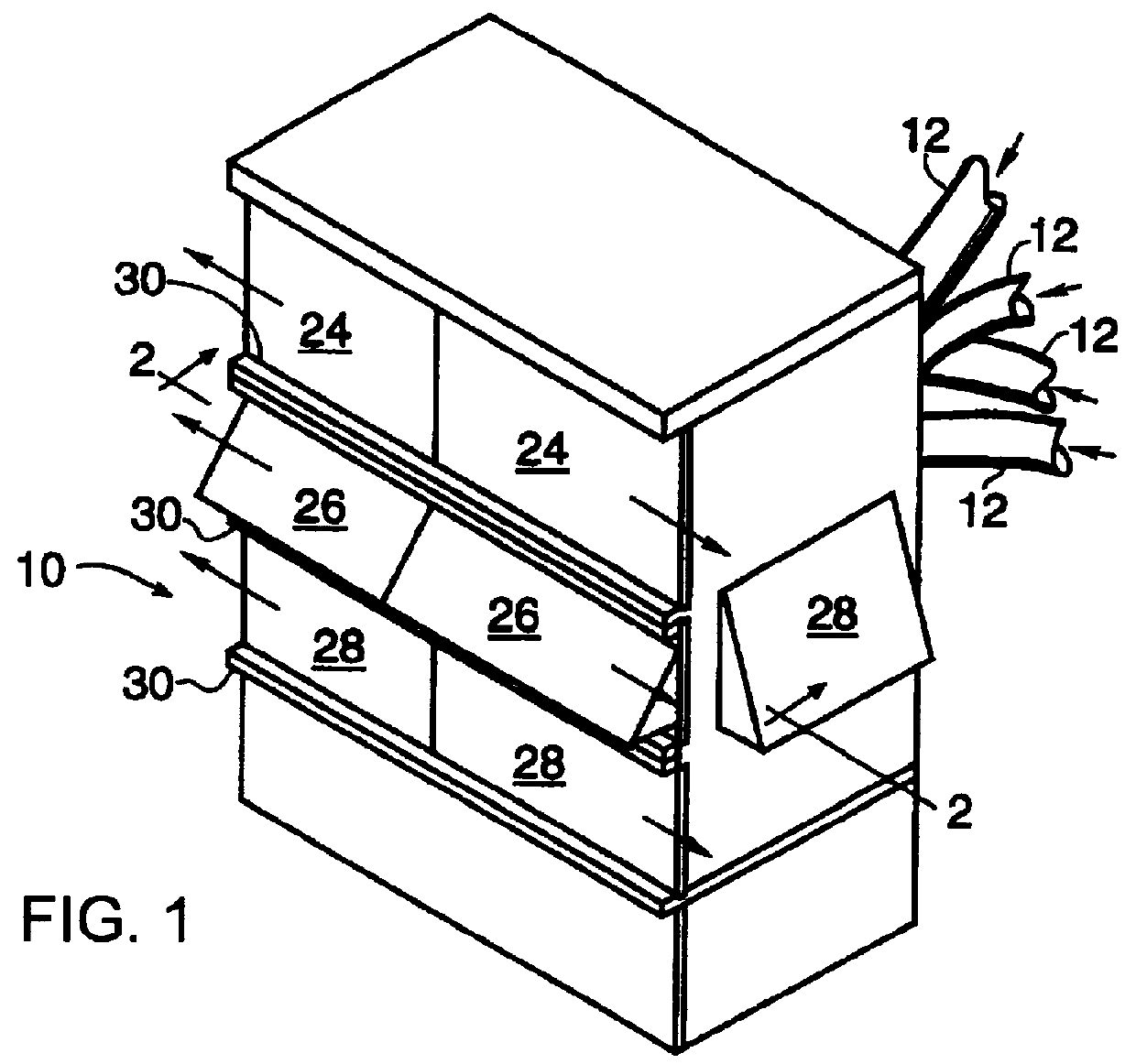
Frosted glass was found to dampen the effect of the filters. For instance, the presence of the frosted glass reduced the systems' ability to produce different lens powers by varying the light (see Example 1 and FIG. 1).
6. In FIG. 3 the center lights 40 are shown in a triangular arrangement when viewed from the side. These lights were rearranged to provide an in-line arrangement.
If the lens edge is incompletely cured (i.e., liquid or gel is still present) while conductive heat is applied, there may be a
high incidence of premature release of the lens from the heating unit.

