
Method for separating wafers from a wafer support and device therefor

A technology for wafers and supporting devices, which can be used in fine working devices, adhesive heating bonding methods, semiconductor/solid-state device manufacturing, etc., and can solve problems such as unfavorable wafers

Inactive Publication Date: 2011-09-14
GEBR SCHMID GMBH & CO
View PDF7 Cites 2 Cited by
  • Summary
  • Abstract
  • Description
  • Claims
  • Application Information

AI Technical Summary

Problems solved by technology

This vertical movement of the wafer on the support is considered disadvantageous as it is a mechanical load

Method used


Image

  • Method for separating wafers from a wafer support and device therefor
  • Method for separating wafers from a wafer support and device therefor
  • Method for separating wafers from a wafer support and device therefor

Examples


Embodiment Construction

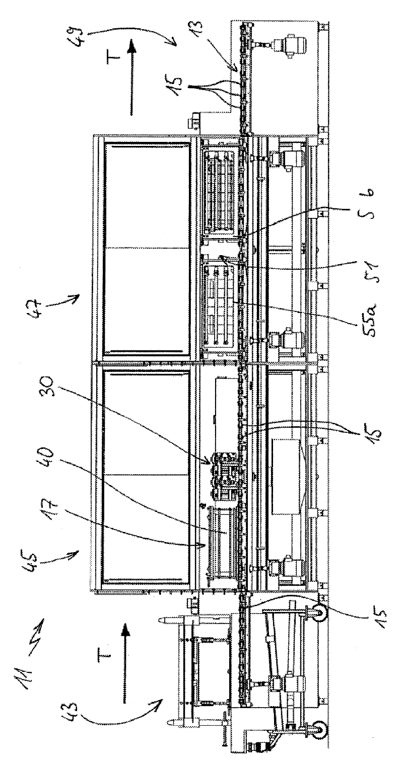
[0022] exist figure 1 The entire device 11 according to the invention is shown in side view. In this process not only the sawn wafer blocks 40 are cleaned, but mainly also debonding according to the invention, ie the individual sawn wafers are separated from the rods or stringers of the support device 17 on which the wafers are also bonded. This device 11 advantageously has a chamber surrounding it. On the far left, it has a drive-in module 43 , by means of which the cage-shaped support device 17 is brought close to the device 11 with the wafer blocks 40 located therein and then driven in. It can be seen here that the entry module 43 has rollers 15 which form roller tracks with other rollers 15 at the level of the conveyor belt 13 . The rollers are advantageously driven individually or collectively. Here too, the above-described transport of wafer pieces 40 horizontally can also be carried out.

[0023] As shown and easily imagined, the cleaning module 45 consists of a clo...


PUM


Abstract

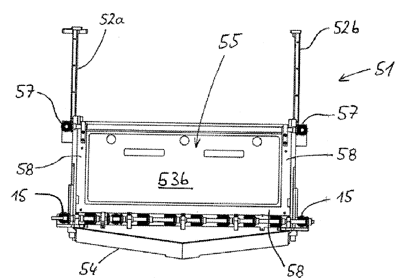
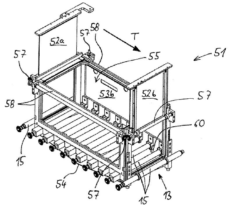
In a method for separating wafers from a support device (17), wherein the wafers are formed by sawing a wafer block (40) fastened to the support device (17) by way of adhesives, and wherein the wafers themselves are still adhering on one side, the support device (17) with the wafers is driven along a constant plane of motion into an adhesive removal device (47). The support device remains therein and is enclosed in an adhesive removal basin (55, 55a, 55b) by moveable wall parts (52a, 52b). After forming and closing the adhesive removal basin (55, 55a, 55b), solvent for removing the adhesive is placed in the adhesive removal basin and onto the wafers for dissolving the adhesive and then removing the wafers from the support device (17).

Description

technical field [0001] The invention relates to a method for separating a wafer from a support device or a so-called rod fixed on the support device, wherein the wafer is formed by sawing a wafer block bonded to the support device or rod and is also bonded on one side with Bonding of support. The invention also relates to a device for carrying out such a method. Background technique [0002] From DE 10 2008 028 213 A it is known to glue a wafer block firmly to a rod and then to fasten this rod to a carrier. The wafer block can then be transported via the support device for further processing. In particular, the wafer block is sawn into individual thin wafers, and the wafers are then also glued via their upper edges to the rod. After the wafer has been cleaned, the wafer is separated from the rod for subdivision and further processing, where the adhesive can be dissolved by a solvent. [0003] For such a debonding process, the wafers including the carrier are generally tr...

Claims


Application Information

Patent Timeline
Patent Type & Authority Applications(China)
IPC IPC(8): B28D5/00
CPCB28D5/0082Y10T29/49821Y10T29/53C09J5/06H01L21/67092H01L21/67126H01L21/6776
Inventor G.沃尔贝尔J.拉姆普雷希特D.普劳尔恩L.沃尔贝尔M.沃尔贝尔H.-J.沃尔贝尔
Owner GEBR SCHMID GMBH & CO
Learn More