Hydraulic locking structure for numerical control milling and drilling machine

A locking structure, drilling and milling machine technology, applied in metal processing equipment and other directions, can solve problems such as being unsuitable for enterprise processing and production, and the self-locking function of the servo motor cannot ensure the spindle quickly, effectively and accurately, and achieves simple structure and stable operation. , the effect of improving production efficiency

Inactive Publication Date: 2013-03-27
WUXI HUALIAN PRECISION MACHINERY
View PDF0 Cites 0 Cited by
  • Summary
  • Abstract
  • Description
  • Claims
  • Application Information

AI Technical Summary

Problems solved by technology

However, due to the large vibration of the workpiece during milling, the self-locking function of the servo motor cannot quickly, effectively and accurately ensure that the spindle does not move when processing the workpiece, which is not suitable for the processing and production requirements of enterprises.

Method used


Image

  • Hydraulic locking structure for numerical control milling and drilling machine

Examples


Embodiment Construction

[0009] The present invention will be further described below in conjunction with specific drawings and embodiments.

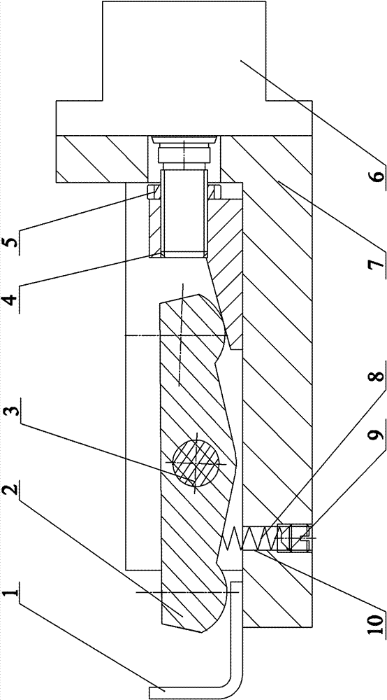
[0010] As shown in the figure, the present invention mainly consists of locking bar 1, jaw bridge plate 2, jaw pin shaft 3, oblique wedge plate 4, round nut 5, oil cylinder 6, jaw body 7, locking spring 8, tightening Screw 9 is formed with parts such as back-moving spring hole 10.

[0011] The hydraulic locking structure of the CNC drilling and milling machine includes a locking oil cylinder 6 fixedly installed at one end of the jaw body 7, a locking bar 1 is installed at the other end of the jaw body 7, and a lock bar 1 is installed between the locking oil cylinder 6 and the locking cylinder 6. The jaw body 7 between the bars 1 is hinged with a jaw bridge plate 2, and a slanted wedge plate 4 is fixedly installed on the piston rod of the locking cylinder 6, and the slanted wedge plate 4 is inserted into one end of the jaw bridge plate 2. Between the jaw body 7...


PUM


Abstract

The invention relates to a hydraulic locking structure for a numerical control milling and drilling machine. A locking cylinder is fixedly arranged at one end part of a jaw body, the other end of the jaw body is provided with a locking strip, a jaw bridge plate is hinged on the jaw body arranged between the locking cylinder and the locking strip, a piston rod on the locking cylinder is fixedly provided with a wedge plate, the wedge plate is inserted between one end part of the jaw bridge plate and the jaw body, the other end part of the jaw bridge plate is arranged on the locking strip; and the jaw body is provided with a resetting mechanism for the jaw bridge plate. The hydraulic locking structure provided by the invention has a simple structure and runs steadily and reliably. By adopting the structure provided by the invention, the defect that a workpiece vibrates when being drilled and milled can be overcome when the cylinder is started; and a hydraulic system is adopted to control compacting and loosening of the cylinder, thus being more practical and more efficient and saving more time and labour, and the production efficiency is improved.

Description

technical field [0001] The invention relates to a device used on a numerically controlled drilling and milling machine to realize locking and positioning of the main shaft base in the transverse direction, the longitudinal direction and the feeding direction, in particular to a hydraulic locking structure of the numerically controlled drilling and milling machine. Background technique [0002] In the existing technology, the locking and positioning of the main shaft often adopt the self-locking function of the servo motor. However, due to the large vibration of the workpiece during milling, the self-locking function of the servo motor cannot quickly, effectively and accurately ensure that the spindle does not move when processing the workpiece, which is not suitable for the processing and production requirements of enterprises. Contents of the invention [0003] The object of the present invention is to overcome the deficiencies in the prior art and provide a hydraulic lo...

Claims


Application Information

Patent Timeline
Patent Type & Authority Patents(China)
IPC IPC(8): B23B19/02
Inventor 陆松茂邵燕瑛薛静清陆坤铭张巍文周冰峰
Owner WUXI HUALIAN PRECISION MACHINERY
Why Eureka
Try Eureka