Novel fan motor

A fan motor, a new technology, applied in the direction of electromechanical devices, electrical components, electric components, etc., can solve the problems of high friction force, low safety, and large motor noise, so as to reduce the friction force of rotation and facilitate installation , the effect of easy installation

Pending Publication Date: 2022-05-10
宁波朝一电子有限公司
View PDF7 Cites 0 Cited by
  • Summary
  • Abstract
  • Description
  • Claims
  • Application Information

AI Technical Summary

Problems solved by technology

[0003] 1. When the rotating shaft rotates at a low speed, due to the short distance between the two bearings on the rotating shaft, the rotating shaft will shake, causing the fan blades to shake accordingly, resulting in high power consumption of the fan;
[0004] 2. The friction force of the motor shaft is large when it rotates, which affects the service life of the motor; and the noise of the motor is large, which reduces the user experience;
[0005] 3. The installation of the motor is not convenient enough, the stability is not enough, and the safety in use is not high

Method used


Image

  • Novel fan motor
  • Novel fan motor
  • Novel fan motor

Examples


Embodiment 1

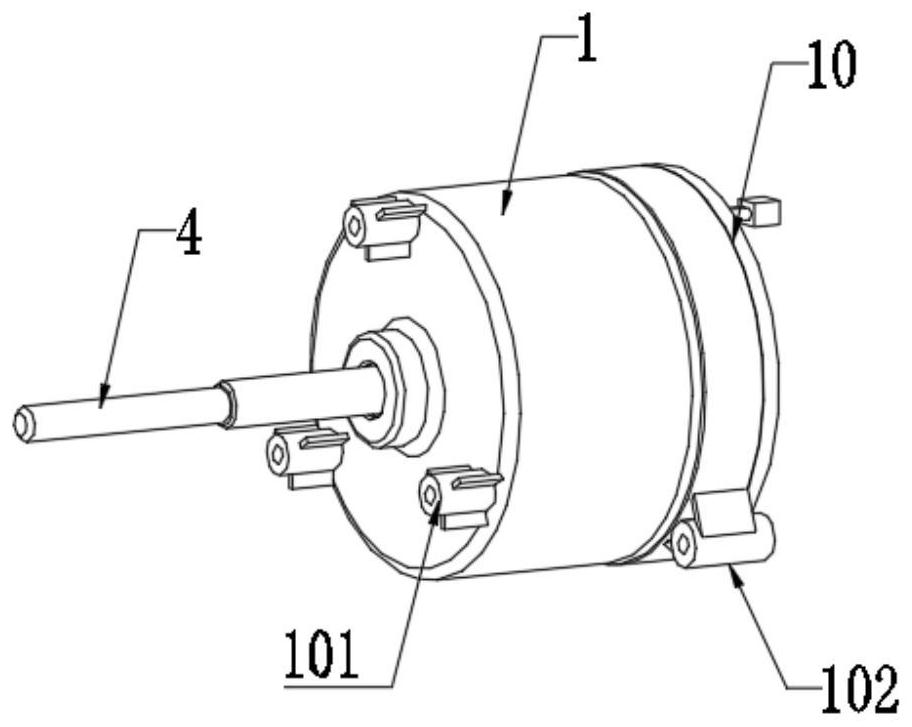
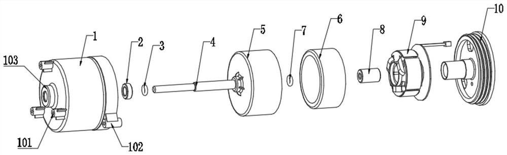
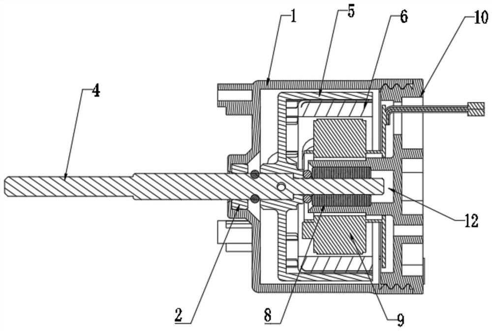
[0034] refer to Figure 1-4 , a new type of fan motor, including an outer cover 1, a first bearing 2, a first silicone ring 3, a rotating shaft 4, a magnetic ring seat 5, a magnetic ring 6, a second silicone ring 7, a second bearing 8, a DC spindle 9 and Motor base 10; threaded connection between the outer cover 1 and the motor base 10;

[0035] The DC spindle 9 is fixed on the motor base 10, the magnetic ring 6 is arranged in the magnetic ring base 5, and the magnetic ring 6 and the magnetic ring base 5 are kept coaxially connected; the magnetic ring base 5 and the magnetic ring 6 are sleeved on the DC spindle 9 On the outside, the rotating shaft 4 is penetrated and fixed on the magnetic ring seat 5, and the right end of the rotating shaft 4 is connected to the DC spindle 9 through the second bearing 8 for rotation;

[0036] A bearing installation part 103 is provided in the middle part of one side of the outer cover 1, and the bearing installation part 103 is a cylindrical ...

Embodiment 2

[0055] refer to Figure 5-6 , the present embodiment adds the following technical solution on the basis of the first embodiment: the rear side end of the motor base 10 and the cover 1 is provided with an oscillating bracket fixing mechanism;

[0056] The oscillating head bracket fixing mechanism includes two oscillating head bracket fixing posts 102 symmetrically arranged on the right side of the outer cover 1 and the mounting hole 11 on the right side of the motor base 10. There are threaded holes inside, the mounting hole 11 and the oscillating head bracket fixing column 102 are on the same vertical plane, and the mounting hole 11 and the two oscillating head bracket fixing columns 102 form an isosceles triangle mounting bracket, through the stability of the triangle, Thereby, the connection between the motor and the oscillating device is more stable, and the shaking of the motor and the fan is reduced.

[0057] The right side end of the motor base 10 is also provided with ...


PUM


Abstract

The invention discloses a novel fan motor, which relates to the technical field of motors and comprises an outer cover, a first bearing, a first silica gel ring, a rotating shaft, a magnetic ring seat, a magnetic ring, a second silica gel ring, a second bearing, a direct current spindle and a motor seat, the outer cover is in threaded connection with the motor base; the direct-current spindle is fixed on the motor base, the magnetic ring is arranged in the magnetic ring base, the magnetic ring base and the magnetic ring are arranged on the outer side of the direct-current spindle in a sleeving mode, the rotating shaft is fixed to the magnetic ring base in a penetrating mode, and the right side end of the rotating shaft is rotationally connected into the direct-current spindle through a second bearing. The outer cover and the motor base are arranged on the outer side of the magnetic ring base and the outer side of the direct-current spindle, the first bearing and the second bearing are arranged at the joint of the rotating shaft and the outer cover and the joint of the rotating shaft and the direct-current spindle respectively, and due to the arrangement of the outer cover, the distance between the two bearings is increased; therefore, the phenomenon that the rotating shaft shakes when the rotor rotates at a low speed is solved, and the power-saving effect is achieved.

Description

technical field [0001] The invention relates to the technical field of motors, in particular to a novel fan motor. Background technique [0002] The motor refers to an electromagnetic device that realizes the conversion or transmission of electric energy according to the law of electromagnetic induction; at present, the motor used in the fan generally suffers from the following problems: [0003] 1. When the rotating shaft rotates at a low speed, due to the short distance between the two bearings on the rotating shaft, the rotating shaft will shake, causing the fan blades to shake accordingly, resulting in high power consumption of the fan; [0004] 2. The friction force of the motor shaft is large when it rotates, which affects the service life of the motor; and the noise of the motor is large, which reduces the user experience; [0005] 3. The installation of the motor is not convenient enough, the stability is insufficient, and the safety during use is not high. [0006...

Claims


Application Information

Patent Timeline
Patent Type & Authority Applications(China)
IPC IPC(8): H02K5/24H02K5/16H02K5/15H02K5/04
CPCH02K5/24H02K5/15H02K5/04H02K5/16
Inventor 张圣甲
Owner 宁波朝一电子有限公司
Why Eureka
Try Eureka