

Double-hearth continuous rare earth carburizing equipment and process thereof
A double furnace, furnace technology, applied in metal material coating technology, coating, solid-state diffusion coating, etc., can solve the problems of fatigue damage and life reduction of workpieces, and achieve shortened carburizing cycle, improved performance and life, and energy saving The effect of reducing consumption and reducing emissions
Inactive Publication Date: 2011-09-21
哈尔滨意锋稀土材料开发有限公司
View PDF5 Cites 4 Cited by
- Summary
- Abstract
- Description
- Claims
- Application Information
AI Technical Summary
Problems solved by technology
[0004] In order to overcome the mutual interference of the carbon potential of the furnace gas between the areas where the through-type continuous operation gas carburizing furnace exists, the carburizing exhaust gas in the middle of the furnace needs to be burned from the exhaust points of the front and rear exhaust ports to avoid pol
Method used
View moreImage
Smart ImageViewing Examples

Examples
 PUM
| Property | Measurement | Unit |
|---|---|---|
| Seepage depth | aaaaa | aaaaa |
| Seepage depth | aaaaa | aaaaa |
| Diameter | aaaaa | aaaaa |
Abstract
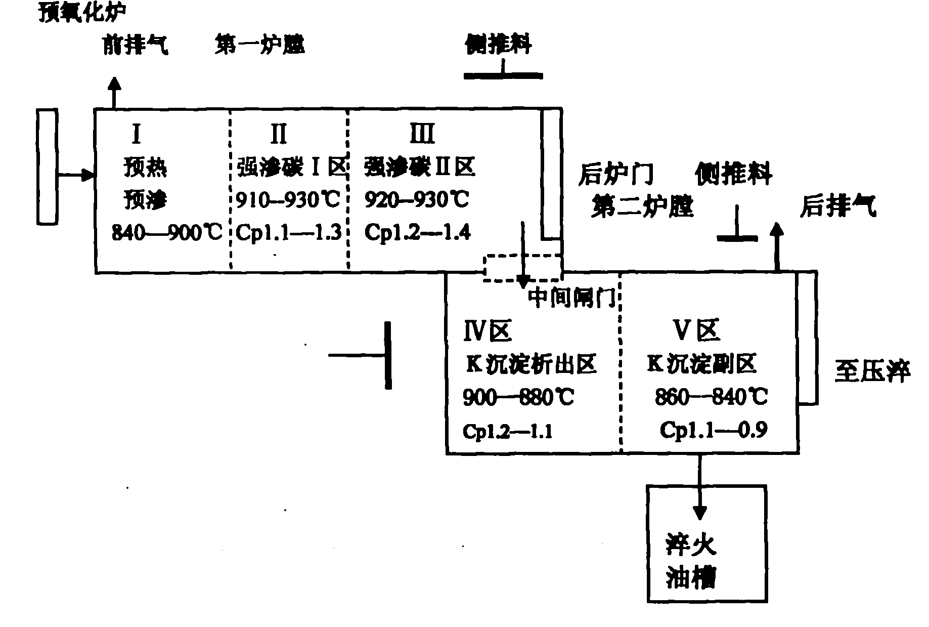
The invention discloses a process of a double-hearth continuous rare earth carburizing equipment. A through type continuous rare earth carburizing furnace comprises double hearths which are arranged in a Z shape, wherein a first hearth is a carburizing speed control hearth and is divided into I, II and III zones; and a second hearth is a carburized layer structure control hearth and is divided into IV and V zones. The two hearths are communicated or partitioned through a gate, and a material tray in the III zone is pushed to the IV zone by utilizing a transverse material-pushing mechanism. Operation parameters of basic processes of the zones are that: in the first hearth, the temperature of the zone I is 860 to 880 DEG C, and Cp is uncontrolled; the temperature of the zone II is 920 DEG C, and Cp is 1.20-1.25 percent; and the temperature of the zone III is 930 DEG C, and Cp is 1.30 to 1.4 percent; in the second hearth, the temperature of the zone IV is 880 to 890 DEG C, and the Cp is 1.1 to 1.2 percent; and the temperature of the zone V is 860 to 840 DEG C, and Cp is 0.9 to 1.0 percent. The carbon potential control accuracy of furnace gas is improved and the mutual interference is reduced, so the setting and adjustment of process parameters are simpler and easier, and the stability and reliability of process operation are greatly improved. By the process, the carburizing cycle is further shortened, and the work efficiency is improved by over 30 percent; moreover, the optimal metallographic structure is easy to obtain, so that the service life of a product is prolonged.
Description
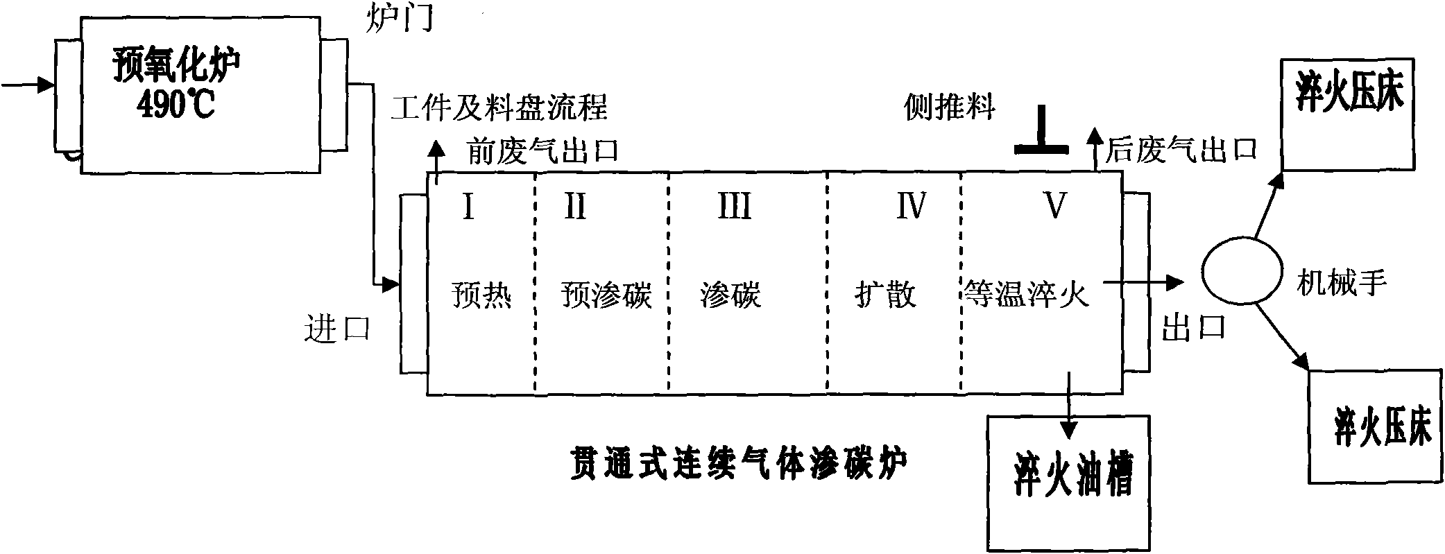
Technical field: [0001] The invention relates to a double furnace type continuous rare earth carburizing equipment and its technology. Background technique: [0002] In order to mass-produce chemical heat treatment of gears, etc., heat treatment processing enterprises generally use through-type continuous operation gas carburizing furnaces for production. Workpieces are mounted on the tray, which is arranged sequentially from the feed end to the discharge end, and at regular intervals such as 30 minutes, 45 minutes or 60 minutes, the push rod mechanism pushes the tray forward one step. The workpiece is carburized in the furnace, and the time of the pushing cycle is determined according to the number of trays, the depth of the carburized layer and the carburized speed. According to the step-by-step push method to the discharge end. It can be quenched after being released from the furnace. When press quenching is required, the manipulator will take it out from the material ...
Claims
Login to View More Application Information
Patent Timeline
 IPC IPC(8): C23C8/22
Inventor刘志儒闫牧夫刘成友吕军成张国良王德欣王佰昕王鸿春唐宏伟
Owner哈尔滨意锋稀土材料开发有限公司