Sound shielding structure and sound shielding cover

A sound-insulating and structural technology, applied in the direction of sound-absorbing devices, engine components, machines/engines, etc., can solve the problems of sound-insulating performance deterioration and weight increase, and achieve the effect of improving sound-insulating performance

Active Publication Date: 2013-06-19
KOBE STEEL LTD
View PDF8 Cites 0 Cited by
  • Summary
  • Abstract
  • Description
  • Claims
  • Application Information

AI Technical Summary

Problems solved by technology

The vibration transmitted to the sound insulation cover due to the phenomenon of resonance transmission is re-radiated from the sound insulation cover, so the sound insulation performance deteriorates
[0010] To solve this problem, the current countermeasures are to insert an attracting material between the noise generating source and the sound insulation cover, or to increase the weight of the sound insulation cover, etc., but these will lead to an increase in weight. From the perspective of energy saving, it is in line with the trend of reducing weight on the contrary

Method used


Image

  • Sound shielding structure and sound shielding cover
  • Sound shielding structure and sound shielding cover
  • Sound shielding structure and sound shielding cover

Examples


no. 1 approach

[0074] (composition of the vehicle)

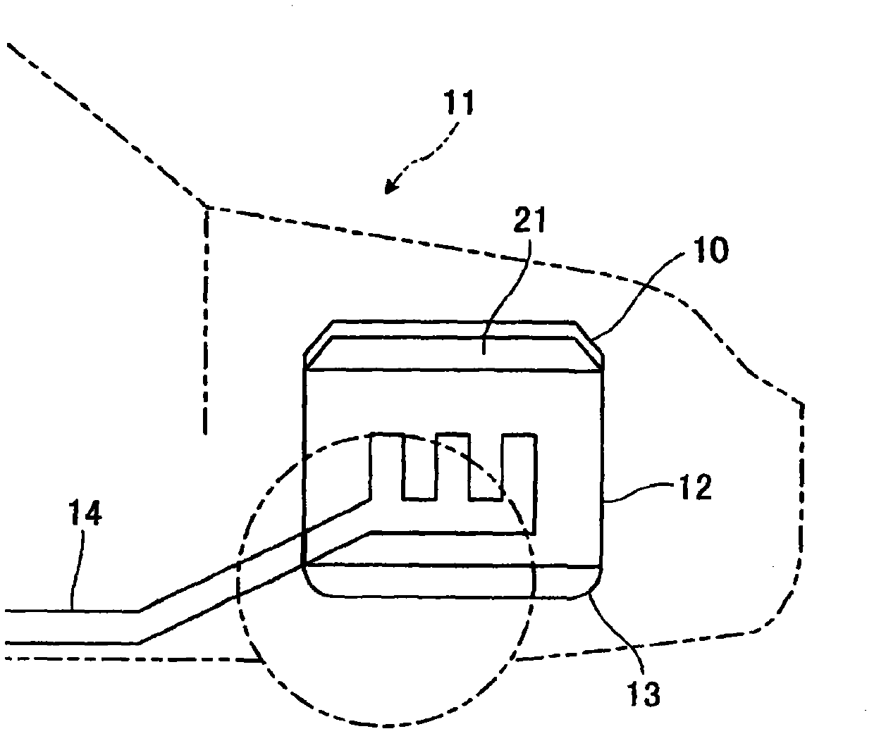
[0075] Such as figure 1 As shown, the engine cover 10 which is the sound insulation cover of this embodiment is installed in the vehicle 11, such as an automobile. The vehicle 11 is provided with an engine 12 , an oil pan 13 for storing engine oil, and an exhaust pipe 14 through which exhaust gas discharged from the engine 12 passes, and these vibrate to generate noise when the engine 12 is in operation. The engine cover 10 of the present embodiment covers the upper surface of the engine 12 as a source of noise via an air layer 21 to block noise from the engine 12 . In addition, the engine cover 10 may cover the entirety of the engine 12 .

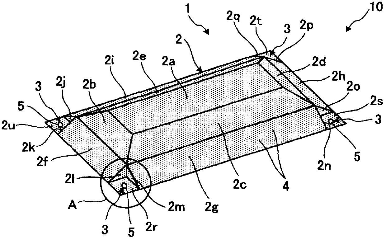
[0076] (The composition of the engine cover)

[0077] Such as figure 2 As shown, the engine cover 10 has a cover main body 2 and a sound insulation structure 1 , and the sound insulation structure 1 has a joint part 3 , and the joint part 3 connects the cover main body 2 and the engine 12 . The c...

no. 2 approach

[0100] Below, combine Figure 8 A second embodiment of the present invention will be described. The difference between the sound insulating structure 51 of the present embodiment and the sound insulating structure 1 of the first embodiment is that joint portions 5 are provided at the four corners of the cover main body 2 .

[0101] The connecting portion 53 has a through hole 56 pierced in the cover main body 2, a pair of fixing members 54a, 54b attached to the through hole 56, and a pair of elastic bodies 55a, 55b provided between the pair of fixing members 54a, 54b.

[0102] A flange portion 58a is provided on the fixing member 54a, and the elastic body 55a is in contact with the flange portion 58a. A flange portion 58b is provided on the fixing member 54b, and the elastic body 55b is in contact with the flange portion 58b. Moreover, the convex part 59a provided in the fixing member 54a is fitted in the recessed part 59b provided in the fixing member 54b. Bolts (fastening...

no. 3 approach

[0108] Next, a third embodiment of the present invention will be described. The engine cover (sound-insulating cover) 110 having the sound-insulating structure 101 of the present embodiment is, for example, Figure 9 As shown, a portion of the engine 112 is covered. The engine cover 110 may cover the entirety of the engine 112 . There is an air layer 21 between the engine 112 and the engine cover 110, and the cover main body 2 and the engine 112 included in the sound insulation structure 101 are coupled by the same coupling portion 53 as in the second embodiment. Also, there is a gap between the end of the cover main body 2 and the engine 112 .

[0109] Such as Figure 10 , Figure 11 As shown, the cover main body 2 is coupled to the convex portion 112 a of the engine 112 through the coupling portion 53 . And a part of the end part 2x of the cover main body 2 is bent toward the direction of the engine 112, and the bent end part 2x is in surface contact with the side surfa...


PUM


Abstract

The present invention provides a sound shielding structure and a sound shielding cover, which can improve the sound shielding performance without weight increase. A split is provided on a cover body (2) around a combination part (3) between an engine and a cover body (2) for reducing the rigidity of the combination part (3). Therefore, a resonance transmission frequency which is determined by theweight of the cover body (2) and rigidity of an air layer and ridigity of the combination part (3) is reduced.

Description

technical field [0001] The present invention relates to a sound-insulating structure and a sound-insulating cover provided near noise sources such as an engine and an exhaust pipe of an automobile. Background technique [0002] When the engine is running in a car, etc., the engine body, oil pan, exhaust pipe, etc. vibrate to generate noise. As such noise countermeasures, various sound-insulating covers that insulate sound in the vicinity of noise generation sources have been proposed. [0003] Patent Document 1 discloses a heat-shielding and sound-shielding cover in which two surface panels and an attractant layer interposed therebetween are each formed into a predetermined planar shape and laminated. The laminated molded flat plate on which the folded portion is formed is molded into the shape of a lid. [0004] In addition, Patent Document 2 discloses an oil pan cover for a vehicle engine in which an opposing flange is formed around the cover main body of the oil pan cov...

Claims


Application Information

Patent Timeline
Patent Type & Authority Patents(China)
IPC IPC(8): F02B77/13F02F7/00F01M11/00F01N13/08
Inventor 山口善三山极伊知郎木村康正
Owner KOBE STEEL LTD
Why Eureka
Try Eureka