

Reducer with bevel gear and cycloid in large transmission ratio for ore grinding machine
A ratio reducer and bevel gear technology, which is applied in the field of mine mill bevel gear-cycloidal large transmission ratio reducer, can solve the problems of novelty and creativity of the invention concept
Inactive Publication Date: 2011-09-21
吴江科技创业园管理服务有限公司
View PDF5 Cites 12 Cited by
- Summary
- Abstract
- Description
- Claims
- Application Information
AI Technical Summary
Problems solved by technology
The planetary part of the invention is related to ①Cheng Daxian's "Mechanical Design Manual" Volume 3. Figure 14-5-31; ②Zhu Xiaolu's "Gear Transmission Design Manual" Figure 7-23; ③"Suspension Balanced Planetary Gear Reducer" 95243413.X; ④ Figure 8-4 of Zhang Zhan's "Planetary Differential Transmission Device";
Method used
View moreImage
Smart ImageViewing Examples

Examples
specific Embodiment approach
Login to View More PUM
 Abstract
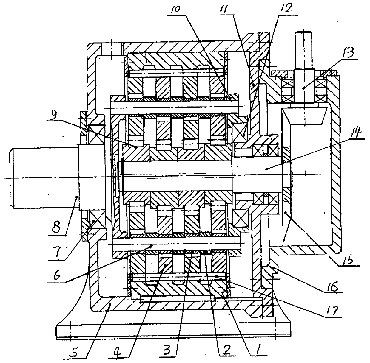
The invention relates to the technical field of reducing the speed of an ore grinding machine. A reducer with a bevel gear and a cycloid in a large transmission ratio for an ore grinding machine is characterized by comprising a bevel gear pair and a cycloid transmission part; the bevel gear pair comprises driving and driven bevel gears; in the cycloid transmission part, (A) needle pin semi-buried holes are uniformly distributed on a needle gear shell, and the needle pins without sleeves are movably matched with the semi-buried holes; (B) a W output mechanism is composed of an output shaft, a column pin, a uniform loading disc and an annular plate; two sides of the W output mechanism are supported on an inner hole of a machine body and the outer circle of a flange in an end cover through bearings; in four single-eccentric bearings, the phase difference between the first bearing and the second bearing and the phase difference between the third bearing and the fourth bearing are 180 DEG and the phase of the second bearing is same as that of the third bearing. In the invention, the reducer has the beneficial effects as follows: (1) the bearing capability is improved by 2-3 times; (2) the length of the axial direction is reduced by 45-55% and the cost is reduced by 40-50%; (3) the reversed installation service life of a cycloid gear is doubled; and (4) the inertia force and the inertia moment are completely balanced in theory when the reducer is operated.
Description
Mining mill bevel gear - cycloid large transmission ratio reducer technical field The invention relates to the technical field of mine mill deceleration, and relates to a bevel gear-cycloid large transmission ratio reducer for mine mills. Background technique CITIC Heavy Industry Machinery Co., Ltd., Luoyang Mining Machinery Design and Research Institute "Conical Planetary Large Transmission Ratio Reducer for Mining Mill Slow Drive Transmission" 200810231115.8 to meet the needs of mining mill slow drive work. The planetary part of the invention is related to ①Cheng Daxian's "Mechanical Design Manual" Volume 3. Figure 14-5-31; ②Zhu Xiaolu's "Gear Transmission Design Manual" Figure 7-23; ③"Suspension Balanced Planetary Gear Reducer" 95243413.X; ④ Figure 8-4 of Zhang Zhan's "Planetary Differential Transmission Device"; In addition, the invention claims that the transmission efficiency is ≥97%, but Zhu Xiaolu's "Gear Transmission Design Manual" 1030 pages, "Mechanical Transmi...
Claims
Login to View More Application Information
Patent Timeline
 IPC IPC(8): F16H1/28F16H57/02F16H57/08
CPCF16H1/32
Inventor吴声震
Owner吴江科技创业园管理服务有限公司