Energy-saving cooling tower

A cooling tower and bottom basin technology, applied in the field of cooling towers, can solve the problems of power consumption, high use cost, and troublesome cleaning of the cooling tower, and achieve the effects of good cooling effect, high operation efficiency and low use cost.

Inactive Publication Date: 2011-09-21
广东顺德丘菱节能科技有限公司
View PDF8 Cites 8 Cited by
  • Summary
  • Abstract
  • Description
  • Claims
  • Application Information

AI Technical Summary

Problems solved by technology

[0002] Water cooling towers are widely used in electric power, metallurgy, petroleum, chemical industry, machinery and other fields. They mainly use hot water and cold air to fully contact the surface of the filler for heat exchange. Make a fuss about it, that is, increase the concave-convex curve surface of the filler, so that the water will prolong the falling time and have more contact with the air, but because the filler is used for too long, it will cause a series of problems, such as filler aging, collapse, accumulation, clogging, etc., will cause The cooling effect is not ideal, so the user must invest a lot of money to add descaling agents or regularly clean the scale, or replace the packing regularly, which will i

Method used


Image

  • Energy-saving cooling tower
  • Energy-saving cooling tower
  • Energy-saving cooling tower

Examples


Embodiment Construction

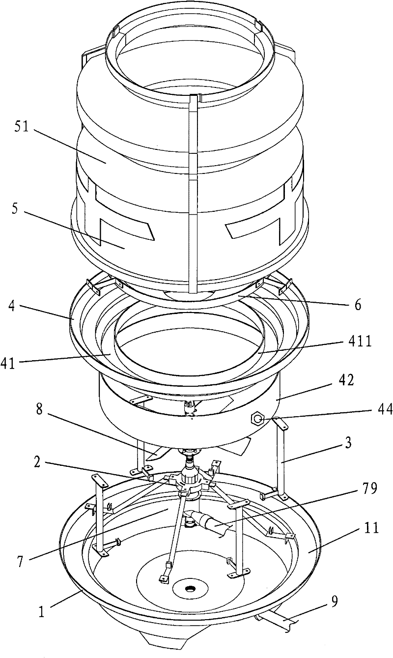
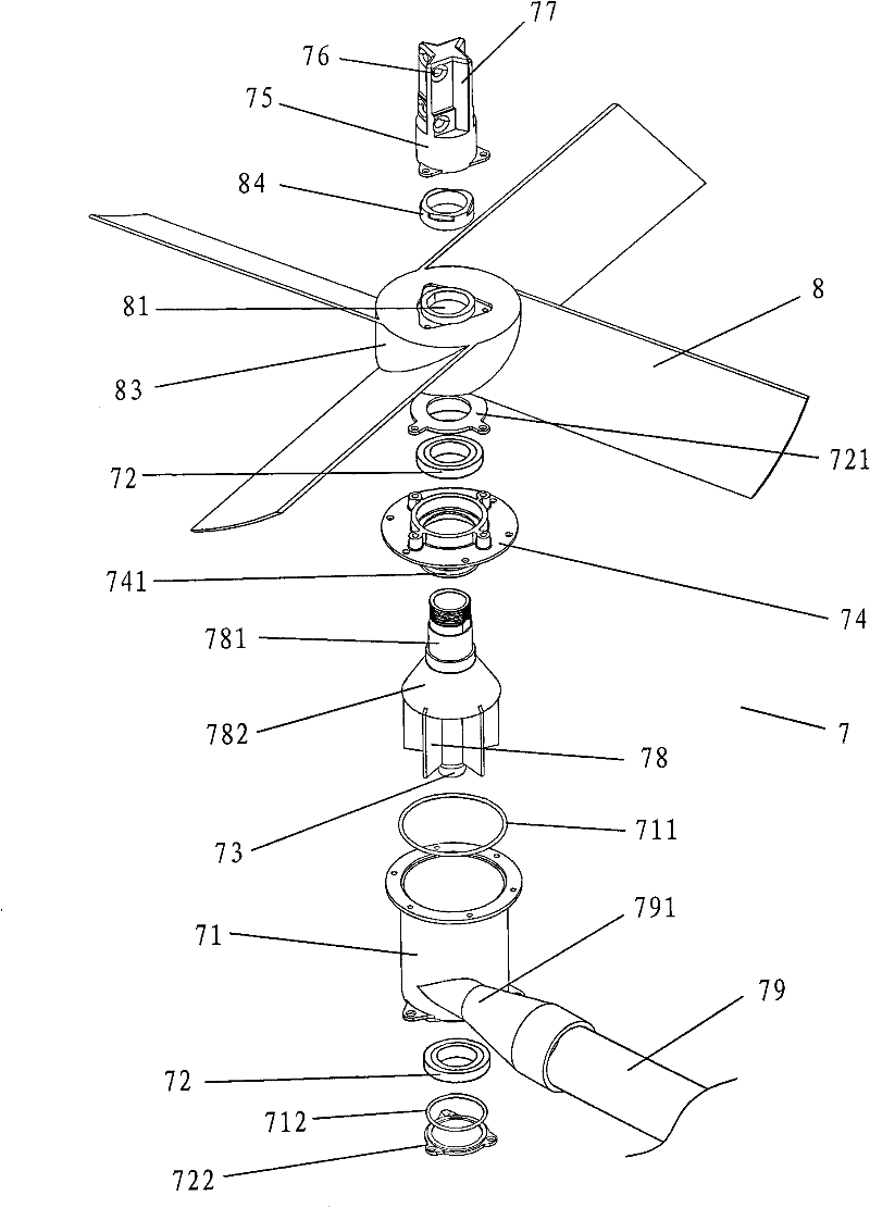
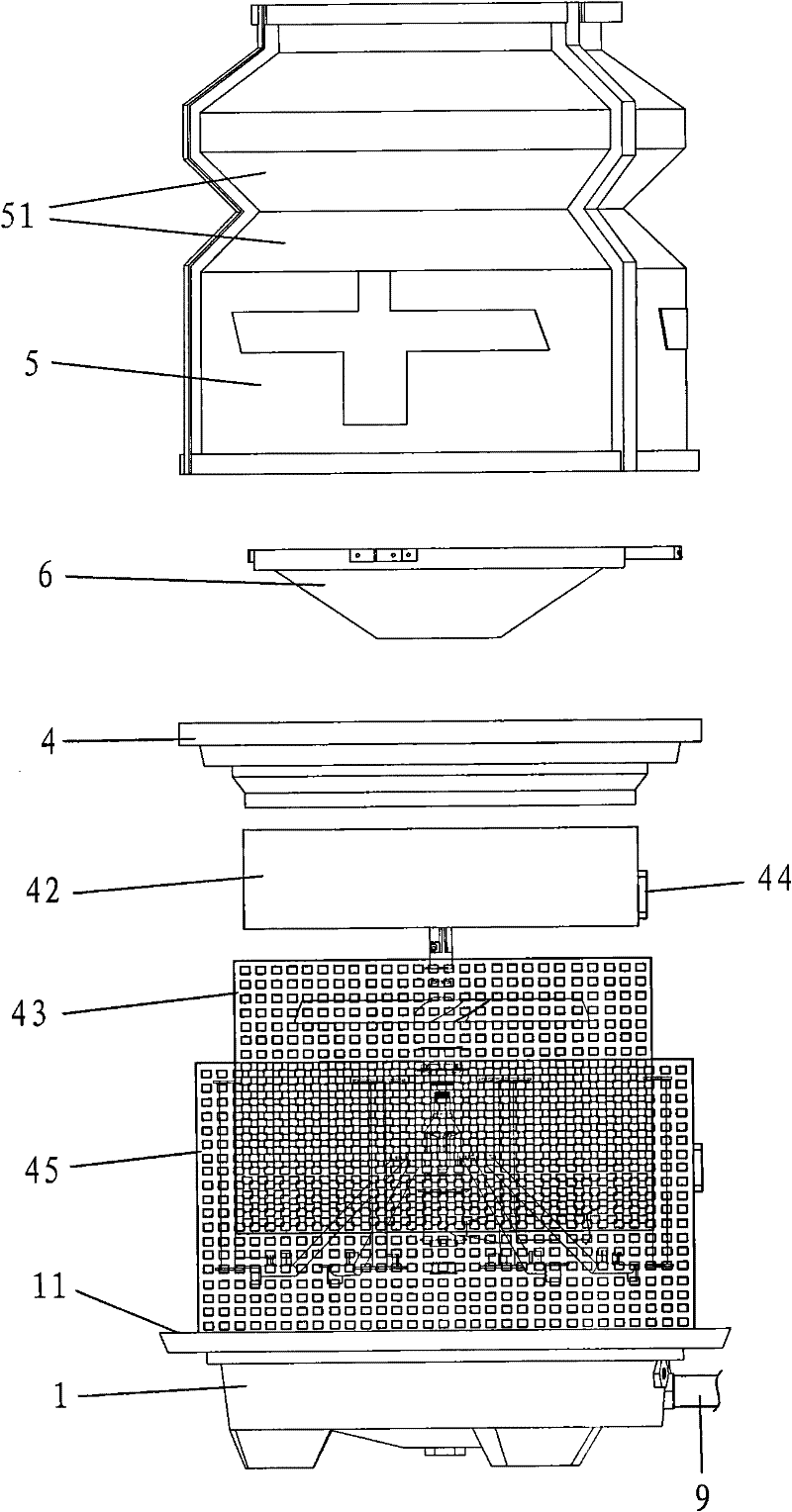
[0013] refer to Figure 1 to Figure 4 , an energy-saving cooling tower of the present invention, comprising a bottom basin 1, a support base 2 is provided in the center of the bottom basin 1, a support frame 3 is provided at the edge, and a water collection basin 4 is provided at the upper end of the support framework 3, and a water collection basin 4 is arranged on Covered with a tower shell 5, the upper part of the tower shell 5 is provided with a water collection cover 6, the support seat 2 is provided with a rotary sprinkler 7, and the rotary sprinkler 7 is equipped with a wind blade 8, and the middle part of the tower shell 5 is provided with There is a concave water collection slope 51, which can collect water well and prevent water droplets from flying out from the top. The water collection cover 6 is in the shape of a funnel and is arranged above the water collection slope 51 to play the role of water collection and return . An annular sump 41 is arranged in the descr...


PUM


Abstract

The invention discloses an energy-saving cooling tower. The energy-saving cooling tower comprises a base basin; a supporting seat is arranged in the center of the base basin; a supporting frame is arranged on the edge of the base basin; a water-collecting basin is arranged at the upper end of the supporting frame; a tower shell is covered on the water-collecting basin; a water-collecting cover is arranged on the upper part in the tower shell; a rotary water sprayer is arranged on the supporting seat; a vane is arranged on the rotary water sprayer; an inward sunken water-collecting slope is formed on the middle part of the tower shell; the water-collecting cover is funnel-shaped and arranged above the water-collecting slope; an annular water-collecting slot is formed in the water-collecting basin; an inner cover is arranged on the inner side of the annular water-collecting slot; a water-collecting ring is arranged on the lower part of the water-collecting basin; a water division inner net is arranged below the water-collecting ring; and an air inlet outer net is arranged between the base basin and the water-collecting basin. The energy-saving cooling tower has a novel structure; the rotation of the vane uses no power, so the energy-saving cooling tower saves much energy, the use cost is lower and the cooling effect is better; moreover, spraying of water from the top can be avoided; the inner air does not flow back; and due to adoption of water flowing on a side net, the energy-saving cooling tower cannot be plugged and the running efficiency is high.

Description

technical field [0001] The invention relates to a cooling tower, in particular to an energy-saving cooling tower. Background technique [0002] Water cooling towers are widely used in electric power, metallurgy, petroleum, chemical industry, machinery and other fields. They mainly use hot water and cold air to fully contact the surface of the filler for heat exchange. To make a fuss about it, that is to increase the concave-convex curve surface of the filler, so that the water prolongs the falling time and has more contact with the air, but because the filler is used for a long time, it will cause a series of problems, such as filler aging, collapse, accumulation, clogging, etc., which will cause The cooling effect is not ideal. Therefore, the user must invest a lot of money to add descaling agents or regularly clean the scale, or replace the packing regularly, which will inevitably increase the maintenance cost. Because the cooling effect of this type of tower is unstable,...

Claims


Application Information

Patent Timeline
IPC IPC(8): F28C1/00F28F25/04F28F25/06F03B3/00
CPCY02E10/223Y02E10/20
Inventor 丘新贵
Owner 广东顺德丘菱节能科技有限公司
Why Eureka
Try Eureka