Line voltage compensation circuit based on peak detection current mode switch circuit

A peak detection circuit, line voltage compensation technology, applied in the direction of conversion equipment without intermediate conversion to AC, can solve the problem that the peak inductor current cannot become a constant value, etc., to overcome the instability of the peak inductor current and the constant peak inductor current. Change and reflect the effect of fast speed

Active Publication Date: 2013-11-06
MAXIC TECHNOLOGY CORPORATION
View PDF4 Cites 0 Cited by
  • Summary
  • Abstract
  • Description
  • Claims
  • Application Information

AI Technical Summary

Problems solved by technology

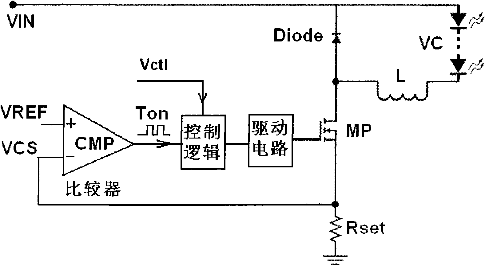
[0010] It can be known from formula (2) that the actual peak inductor current Ipk varies linearly with the input voltage VIN. Therefore, although the traditional peak-sensing current-mode switching circuit has certain advantages, due to the inherent delay of the traditional peak-sensing current-mode switching circuit system, The inductor peak current cannot become a constant value in the true sense, and the inductor peak current is higher than ideal and will vary with the supply voltage VIN

Method used


Image

  • Line voltage compensation circuit based on peak detection current mode switch circuit
  • Line voltage compensation circuit based on peak detection current mode switch circuit
  • Line voltage compensation circuit based on peak detection current mode switch circuit

Examples


Embodiment Construction

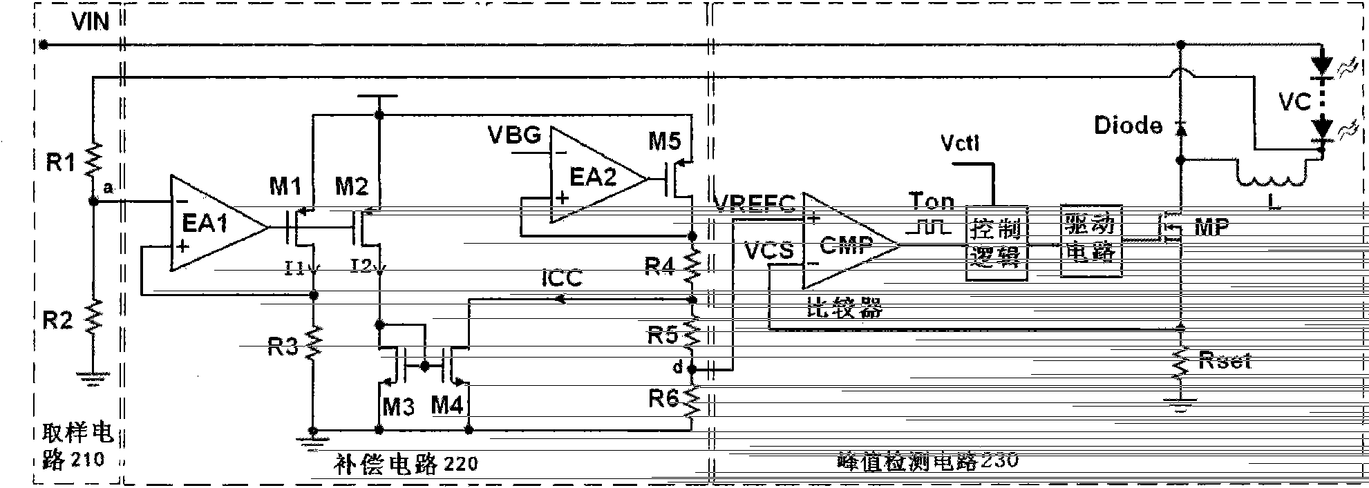
[0028] figure 2 It is a block diagram of the line voltage compensation circuit. The line voltage compensation circuit 200 includes a sampling circuit 210 and a compensation circuit 220 .

[0029] The sampling circuit 210 is used for sampling a voltage proportional to the line voltage VIN, so as to obtain a proportionally reduced sampling voltage that is linearly related to the line voltage VIN.

[0030] The compensation circuit 220 is connected to the sampling circuit 210, and is used to compensate the sampling voltage output by the sampling circuit 210 to the peak detection circuit 230 as an electrical signal, so that the inductor peak current is equal to the ideal inductor peak current IPK0. In one embodiment of the present invention, the compensation circuit 220 is used for converting the sampling voltage output by the sampling circuit 210 into a sampling current, and compensating the sampling current to the peak detection circuit 230 in the form of voltage. In another e...


PUM


Abstract

The invention relates to a line voltage compensation circuit based on peak detection current mode switch circuit. The line voltage compensation circuit provided by the invention comprises a sample circuit and a compensation circuit, wherein, the sample circuit is used for sampling voltages related with the line voltage, thus obtaining sampling voltages which are in linear relation with the line voltage and scaling down in proportion. The compensation circuit is connected with the sample circuit and is used for compensating the non-inverting input end or inverted input end of a comparator in the peak detection circuit by utilizing the sampling voltage of the output by the sample circuit in an electrical signal mode, so that the inductance peak point current is equal to the inductance peak point current under the ideal situation. The line voltage compensation circuit provided by the invention not only has the advantages of steady loop and quick reaction speed and the like in the traditional peak detection current mode switch control circuit, but also can be used for overcoming the problem of unstable inductance peak point current caused by system delay, so that the inductance peak point current is invariant. The line voltage compensation circuit provided by the invention can be widely applied to analogue integrated circuits.

Description

technical field [0001] The invention relates to an analog integrated circuit, in particular to a peak detection current type switching circuit. Background technique [0002] The peak detection current switch control method is a commonly used method to control the peak current in the power system. The basic principle is to detect the inductor current value in real time through the comparator in the peak detection current switch circuit and then control the peak value of the inductor current to be constant. value. [0003] figure 1 It is the structural diagram of the traditional peak detection current-type switch control circuit. The loop structure of the peak detection current-type switch control circuit is simple, no loop compensation is needed, the entire loop is relatively stable, and the response speed is also fast. [0004] figure 1 Among them, the voltage value of several light-emitting diodes is VC. When the power tube MP is turned on, the power supply VIN charges ...

Claims


Application Information

Patent Timeline
Patent Type & Authority Patents(China)
IPC IPC(8): H02M3/06
Inventor 郑儒富景卫兵
Owner MAXIC TECHNOLOGY CORPORATION
Why Eureka
Try Eureka