Electronic compass

A technology of electronic compass and magnetic field strength, applied in directions such as compass, magnetic field size/direction, measuring device, etc., can solve complex and error-prone algorithms and other problems, and achieve the effect of improving robustness

Inactive Publication Date: 2011-09-21
ROBERT BOSCH GMBH
View PDF7 Cites 13 Cited by
  • Summary
  • Abstract
  • Description
  • Claims
  • Application Information

AI Technical Summary

Problems solved by technology

Since 3D magnetic sensor data is directly processed, complex and error-prone algorithms are required

Method used


Image

  • Electronic compass
  • Electronic compass
  • Electronic compass

Examples


Embodiment Construction

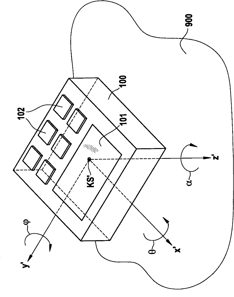
[0026] figure 1 A schematic diagram of electronic compass 100 is shown. The electronic compass 100 may have a screen 101 for displaying an azimuth obtained by the electronic compass 100 . The electronic compass 100 can also have an operating element 102 , for example one or more operating keys. Operating element 102 allows electronic compass 100 to be operated. The electronic compass 100 can be integrated into another portable or non-portable electronic device, such as a mobile phone, a personal digital assistant (PDA), a navigation device, or a wrist watch.

[0027] The first coordinate system KS′ can be regarded as being fixedly connected to the electronic compass 100 . The first coordinate system KS' has three mutually perpendicular axes x', y', z'. The x' axis points forward from the electronic compass 100, the y' axis points sideways, and the z' axis points down. The rotation of the electronic compass around the x' axis corresponds to the change of the lateral inclin...


PUM


Abstract

The present invention relates to a method for determining a deviation from zero (Hx0, Hy0) of an electronic compass, comprising the steps of determining first magnetic field strengths in a first coordinate system of the electronic compass by means of a three-axis magnetic sensor; calculating inclination-compensated second magnetic field strengths (200) in a second coordinate system (x, y) which is parallel to the surface of the Earth based on the first magnetic field strengths for adjusting an approach function (210) to the inclination-compensated second magnetic field strengths (200); and determining a deviation from zero (Hx0, Hy0) from the adjusted approach function (210). A method for operating the electronic compass comprises steps for calculating an inclination-compensated magnetic field strength (Hx, Hy) in the second coordinate system (x, y) based on a first magnetic field strength measured by the magnetic sensor, for calculating a zero-point corrected third magnetic field strength (Bx, By) by subtracting the deviation from zero (Hx0, Hy0), determined by the aforementioned method, from the inclination-compensated second magnetic field strength (Hx, Hy), and for calculating an azimuth angle by which an axis (x) of the second coordinate system (x, y) deviates in relation to a north-south direction.

Description

technical field [0001] The invention relates to a method for determining the zero offset of an electronic compass, a method for operating an electronic compass, and an electronic compass. Background technique [0002] Magnetic sensors can be used to measure the earth's magnetic field and are therefore suitable for use in electronic compasses. Since the Earth's magnetic field is parallel to the Earth's surface, magnetic sensors are required that can determine the Earth's magnetic field along at least two mutually perpendicular axes. In this case, the electronic compass must be kept parallel to the earth's surface. In the case of a three-axis magnetic sensor, the inclination of the electronic compass relative to the earth's surface can be calculated. [0003] Since the strength of the Earth's magnetic field is in the range of only a few tens of μT, very sensitive magnetic sensors are required, which are susceptible to interference fields. Such disturbance fields can be caus...

Claims


Application Information

Patent Timeline
Patent Type & Authority Applications(China)
IPC IPC(8): G01C17/38
CPCG01C17/38G01R33/0206G01C17/28
Inventor F·本尼尼
Owner ROBERT BOSCH GMBH
Why Eureka
Try Eureka