Gear modeling method and gear modeling device

A modeling method and gear technology, which can be applied to hoisting devices, portable lifting devices, belts/chains/gears, etc., can solve problems such as low modeling accuracy

Active Publication Date: 2011-09-28
BEIJING JINGWEI HIRAIN TECH CO INC
View PDF6 Cites 13 Cited by
  • Summary
  • Abstract
  • Description
  • Claims
  • Application Information

AI Technical Summary

Problems solved by technology

[0009] The present invention aims to provide a gear modeling method and a gear

Method used


Image

  • Gear modeling method and gear modeling device
  • Gear modeling method and gear modeling device
  • Gear modeling method and gear modeling device

Examples


no. 1 example

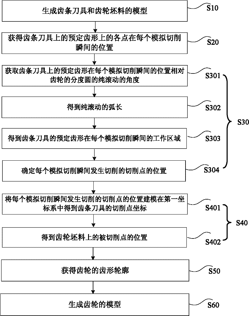
[0062] figure 1 is a flow chart of the gear modeling method according to the first embodiment of the present invention. This embodiment is applicable to the modeling of gears with the same or proportional normal sections. Such as figure 1 As shown, in this embodiment, the gear modeling method includes the following steps:

[0063] Step S10, generating models of the rack cutter and the gear blank. Specifically, this step can be completed by CATIA software. Of course, any other 3D modeling software can also be used.

[0064] Step S20, using the models of the rack cutter and the gear blank, by simulating the cutting movement of the rack cutter relative to the gear blank for gear machining, to obtain the position of each point on the predetermined tooth shape on the rack cutter at each simulated cutting moment.

[0065] Specifically, in step S20 , using the models of the rack cutter and the gear blank generated in step S10 , the cutting movement of the rack cutter relative to...

no. 2 example

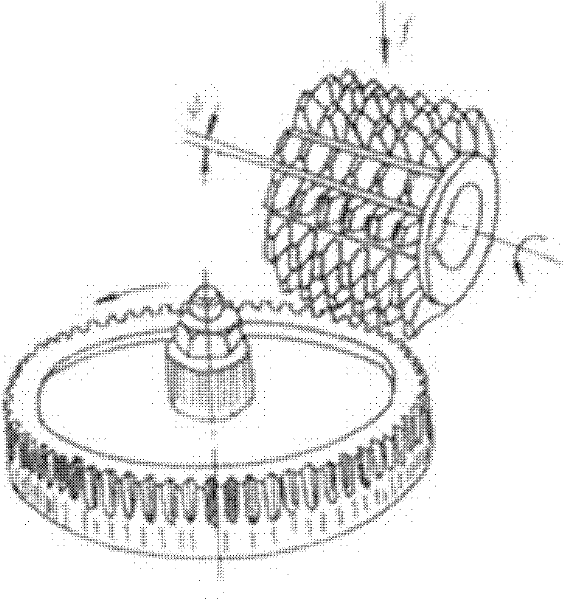
[0136] This embodiment is suitable for modeling of worm gears. Wherein, in this embodiment, the rack cutter is a worm-shaped cutter, and the tooth profile of the worm wheel can be regarded as being enveloped by the worm-shaped cutter. In fact, in any plane that passes through the centerline of the worm-shaped tool, the intersection line of the worm-shaped tool in this plane can be regarded as the tooth profile of a rack tool. Therefore, in this embodiment, the worm wheel modeling process is the same as The gear modeling process shown in Embodiment 1 is similar.

[0137] Figure 14 It is a flow chart of the gear modeling method according to the second embodiment of the present invention, and the second embodiment differs from the first embodiment mainly in steps S30 to S60. Such as Figure 14 As shown, the specific steps of the second embodiment are as follows:

[0138] Step S10 and step S20 are the same as those in the first embodiment, and will not be repeated here.

[0...

no. 3 example

[0203] In this embodiment, a gear modeling device is provided, which can be constructed by hardware circuits for performing various functions, or can be embedded in a computer and realized by software.

[0204] Such as Figure 20 As shown, the device includes:

[0205] The first modeling module 10, is used for generating the model of rack cutter and gear blank;

[0206] The first acquisition module 20 is used to use the model of the rack tool and the gear blank to obtain the points on the predetermined tooth profile on the rack tool by simulating the cutting motion of the rack tool for gear machining relative to the gear blank. The position at the moment of cutting;

[0207] The second acquisition module 30 is used to determine the position of the cutting point where cutting occurs at each simulated cutting instant according to the position of each point on the predetermined tooth profile on the rack cutter at each simulated cutting instant;

[0208] The third acquisition m...


PUM


Abstract

The invention provides a gear modeling method and a gear modeling device, wherein the gear modeling method comprises the following steps of: generating models of a rack cutter and a gear blank; performing cutting motion of gear processing through simulating the rack cutter in relative to the gear blank by using the models of the rack cutter and the gear blank so as to obtain the position of each point on preset gear shape of the rack cutter at each analogue cutting moment; determining the position of a cutting point of cutting at each analogue cutting moment; determining the position of a cutpoint on the corresponding gear blank at each analogue cutting moment so as to obtain a gear shape outline of the gear; and generating the model of the gear according to the gear-shaped outline. The modeling method provided by the invention is capable of truly reflecting the shape of the practically processed tooth root transition curve based on processing and enveloping processes of the rack cutter and capable of realizing turbine modeling; and the modeling precision is high.

Description

technical field [0001] The invention relates to the field of mechanical transmission parts, in particular to a gear modeling method and a gear modeling device. Background technique [0002] With the development of NC machining gear technology, the machining of gears with complex tooth surfaces is gradually realized. However, to process gears with NC technology, it is first necessary to input high-precision coordinate parameters that meet the requirements of NC machining. At present, for some gears with complex tooth surfaces, to obtain the coordinate parameters of the tooth surface, the main method is to solve complex conjugate equations by computer or obtain the cumbersome calculations of intersection and surface bridging by discrete method, which takes too long. Moreover, the precision of the obtained tooth surface is low, which cannot well reflect the meshing quality between complex conjugate tooth surfaces. Therefore, it is becoming more and more necessary to establish ...

Claims


Application Information

Patent Timeline
IPC IPC(8): B23F3/00B23Q33/00F16H55/08F16H55/17
Inventor 程爱明杨轩王文平
Owner BEIJING JINGWEI HIRAIN TECH CO INC
Why Eureka
Try Eureka