Washing machine

A washing machine and detection mechanism technology, which is applied in the field of washing machines, can solve the problems of damper obstruction and inability to obtain attenuation performance, and achieve the effect of stabilizing attenuation performance

Inactive Publication Date: 2011-09-28
TOSHIBA LIFESTYLE PROD & SERVICES CORP
View PDF8 Cites 3 Cited by
  • Summary
  • Abstract
  • Description
  • Claims
  • Application Information

AI Technical Summary

Problems solved by technology

[0032] That is, in the prior art described in the second background art, the damping force D of the damper 16 changes due to the temperature of the environment in which the washing machine is used, especially at

Method used


Image

  • Washing machine
  • Washing machine
  • Washing machine

Examples


no. 2 approach

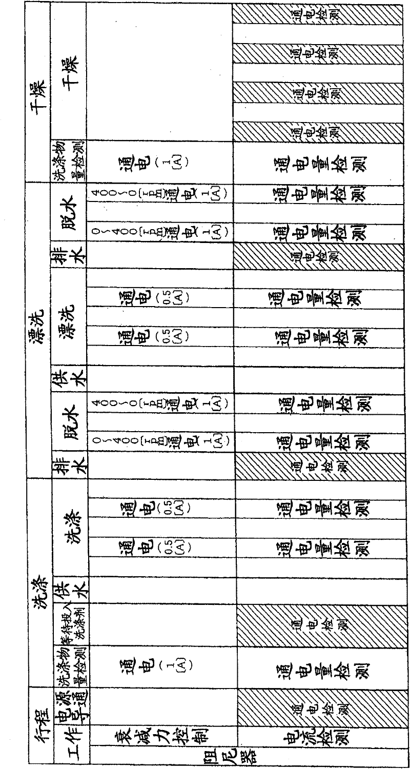
[0180] exist Figure 7 In the shown second embodiment, the energization detection of the damper 21 is carried out between the normal rotation and the reverse rotation of the drum 10 .

[0181] In the work of the "washing" stroke, the work of the "rinsing" stroke, and the work of the "drying" stroke, as described above, the drum 10 is alternately rotated in the forward and reverse directions at a low speed, that is, as Figure 7 As shown in the upper part of , forward rotation and reverse rotation of the drum 10 are alternately performed.

[0182] When the drum 10 alternately performs normal rotation and reverse rotation, as shown in the lower half of the figure, the energization detection of the damper 21 is carried out between the normal rotation and the reverse rotation of the drum 10 .

[0183] Between the forward rotation and the reverse rotation of the above-mentioned drum 10, the drum 10 is temporarily stopped in order to reverse the drum 10. Therefore, in such a case,...

no. 3 approach

[0192] exist Figure 8 In the third embodiment of the present invention shown, when the energization detection of the damper 21 is performed multiple times, it is determined that the energization of the damper 21 is impossible when no energization of the damper 21 is detected multiple times.

[0193] Specifically, in the above Image 6 In steps S3 and S9 in the shown control content, when it is determined that the energization amount is 0A ("Yes", no energization), it is judged whether the number of detections that the energization amount is 0A has reached, for example, three times ( Steps S101, S103), if it is judged that the number of times has not reached 3 ("No"), then return to steps S2, S8 to conduct the energization detection of the damper 21 .

[0194] On the other hand, when it is judged in steps S3 and S9 that the energized amount is not 0A ("No", energized), it is judged whether the number of energized detections has reached 5 times (steps S102, S104), and if it is...

no. 4 approach

[0200] In the fourth embodiment of the present invention shown in FIG. 9 , the energization of the damper 21 when detecting the energization of the damper 21 is compared with the amount of energization of the damper 21 when the damping force of the damper 21 is changed. The power is low.

[0201] In such a case, as shown in FIG. 9(a), when the damping force of the damper 21 is changed, the current flow of the damper 21 (the upper and lower coils 36, 39) is set to A, as shown in FIG. 9(b) ), when the energization amount of the damper 21 is B when the energization detection of the damper 21 is performed, the energization amount A>the energization amount B is energized.

[0202] In this way, the energization detection of the damper 21 can be performed by passing a necessary and sufficiently small current, and the power consumption can be suppressed to be small.

[0203] In addition, in such a case, when the damping force of the damper 21 is changed when the dehydration operation...


PUM


Abstract

The invention provides a washing machine, wherein the conduction detection of a damper is performed without hindering the attenuation force control of the damper. Meanwhile, the conduction detection of the damper is maintained to be constant regardless of the environment temperature. The suspension of an elastic support rotating groove is equipped with a damper for attenuating the vibration of a basin. The damp adopts a functional fluid and the viscosity of the functional fluid is changeable along with the applied power implemented by the energization of a coil. At a timing when the attenuation force of the damper is not changed, the conduction detection of the damper is performed, which will not hinder the attenuation force control of the damper. The energization of the coil is executed before the dehydration stroke (washing stroke), so that the viscosity of a magnetic viscous fluid and the hardness of a sealing member for preventing the leakage of the magnetic viscous fluid during the dehydration stroke at a low temperature are reduced. Therefore, the frictional force for shafts becomes moderate.

Description

technical field [0001] The present invention relates to a washing machine that can be applied to drum-type or vertical-type fully automatic washing machines that use a functional fluid in a damper for absorbing vibration of a water tank. Background technique [0002] As the first background technology, in various washing machines, including drum type washing machines, a water tank is located inside the outer box, and a drum as a rotating tank is located inside the water tank, and the drum is rotated by a motor outside the water tank. drive. [0003] In addition, the water tank is provided on the bottom plate of the outer case to be elastically supported by a suspension, and the suspension has a damper for attenuating the vibration of the water tank accompanying the vibration of the drum. [0004] For this type of damper, a type with a constant damping force is generally used, but in recent years, a type with a variable damping force has also been considered, and the use of ...

Claims


Application Information

Patent Timeline
IPC IPC(8): D06F23/02D06F33/02
CPCD06F37/10D06F37/225D06F37/268D06F37/28D06F37/304D06F39/14D06F33/48D06F34/16E05Y2900/312F16F13/30Y02B40/00
Inventor 久野功二西村隆宏江碕猛大藪起也西村博司
Owner TOSHIBA LIFESTYLE PROD & SERVICES CORP
Why Eureka
Try Eureka