Washing machine
A washing machine and detection mechanism technology, which is applied in the field of washing machines, can solve the problems of damper obstruction and inability to obtain attenuation performance, and achieve the effect of stabilizing attenuation performance
- Summary
- Abstract
- Description
- Claims
- Application Information
AI Technical Summary
Problems solved by technology
Method used
Image
Examples
no. 2 approach
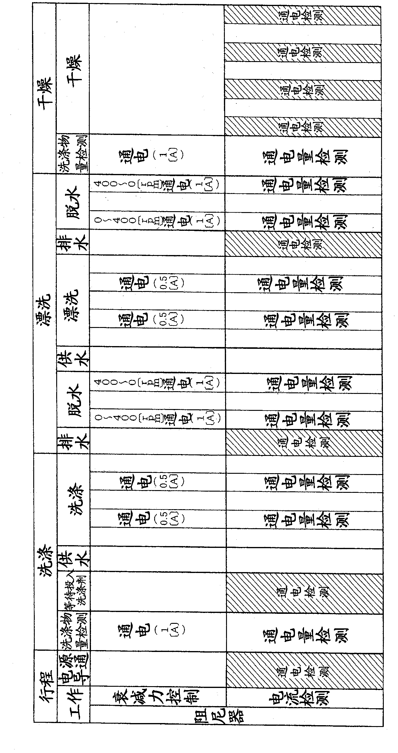
[0181] exist Figure 7 In the shown second embodiment, the energization detection of the damper 21 is carried out between the normal rotation and the reverse rotation of the drum 10 .
[0182] In the work of the "washing" stroke, the work of the "rinsing" stroke, and the work of the "drying" stroke, as described above, the drum 10 is alternately rotated in the forward and reverse directions at a low speed, that is, as Figure 7 As shown in the upper part of , forward rotation and reverse rotation of the drum 10 are alternately performed.
[0183] When the drum 10 alternately performs normal rotation and reverse rotation, as shown in the lower half of the figure, the energization detection of the damper 21 is carried out between the normal rotation and the reverse rotation of the drum 10 .
[0184] Between the forward rotation and the reverse rotation of the above-mentioned drum 10, the drum 10 is temporarily stopped in order to reverse the drum 10. Therefore, in such a case,...
no. 3 approach
[0193] exist Figure 8 In the third embodiment of the present invention shown, when the energization detection of the damper 21 is performed multiple times, it is determined that the energization of the damper 21 is impossible when no energization of the damper 21 is detected multiple times.
[0194] Specifically, in the above Figure 6 In steps S3 and S9 in the shown control content, when it is determined that the energization amount is 0A ("Yes", no energization), it is judged whether the number of detections that the energization amount is 0A has reached, for example, three times ( Steps S101, S103), if it is judged that the number of times has not reached 3 ("No"), then return to steps S2, S8 to conduct the energization detection of the damper 21 .
[0195] On the other hand, when it is judged in steps S3 and S9 that the energized amount is not 0A ("No", energized), it is judged whether the number of energized detections has reached 5 times (steps S102, S104), and if it i...
no. 4 approach
[0201] In the fourth embodiment of the present invention shown in FIG. 9 , the energization of the damper 21 when detecting the energization of the damper 21 is compared with the amount of energization of the damper 21 when the damping force of the damper 21 is changed. The power is low.
[0202] In such a case, as shown in FIG. 9(a), when the damping force of the damper 21 is changed, the current flow of the damper 21 (the upper and lower coils 36, 39) is set to A, as shown in FIG. 9(b) ), when the energization amount of the damper 21 is B when the energization detection of the damper 21 is performed, the energization amount A>the energization amount B is energized.
[0203] In this way, the energization detection of the damper 21 can be performed by passing a necessary and sufficiently small current, and the power consumption can be suppressed to be small.
[0204] In addition, in such a case, when the damping force of the damper 21 is changed when the dehydration operation...
PUM
 Abstract
Description
Claims
Application Information
 - R&D
- Intellectual Property
- Life Sciences
- Materials
- Tech Scout
- Unparalleled Data Quality
- Higher Quality Content
- 60% Fewer Hallucinations
Browse by: Latest US Patents, China's latest patents, Technical Efficacy Thesaurus, Application Domain, Technology Topic, Popular Technical Reports.
© 2025 PatSnap. All rights reserved.Legal|Privacy policy|Modern Slavery Act Transparency Statement|Sitemap|About US| Contact US: help@patsnap.com


