Design method of non-imaging optical element

A technology of non-imaging optics and design methods, applied in optical components, optics, instruments, etc., can solve problems such as difficulty, method popularization, complex mathematical problems, etc.

Active Publication Date: 2013-07-10
SHANGHAI SANSI ELECTRONICS ENG +3
View PDF3 Cites 0 Cited by
  • Summary
  • Abstract
  • Description
  • Claims
  • Application Information

AI Technical Summary

Problems solved by technology

The development of LED lighting makes non-imaging optics expand from solving the problem of effectively collecting solar energy to solving the problem of light energy distribution in a larger range. Mathematical problems, the popularity of the method is not large, and some of the methods also have some shortcomings
For example: 1) It is difficult to solve nonlinear differential equations; 2) Most methods can only solve one surface, which is not an ideal method for lenses with two surfaces; 3) Not intuitive enough

Method used


Image

  • Design method of non-imaging optical element
  • Design method of non-imaging optical element
  • Design method of non-imaging optical element

Examples


Embodiment Construction

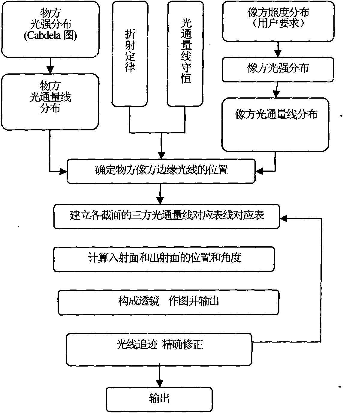
[0050] figure 1 In the flow chart of the design method of the present invention shown, the side of the LED as the light source is called the object side, and the illuminated side is called the image side. The luminous intensity distribution diagram (ie Cabdela diagram) of the known object space is converted into a luminous flux line distribution diagram. The illuminance distribution of the image side is determined according to the user's requirements, and the illuminance distribution is converted into a light intensity distribution map, and then converted into a luminous flux line distribution map. The problem to be solved by the present invention is to use the law of refraction or reflection to obtain the intermediate optical element between the object space and the image space according to the law of conservation of luminous flux, that is, an optical lens or a mirror. The first step is to determine the angles θa and θb of the edge rays of the object space, and the angles of...


PUM


Abstract

The invention discloses a design method of a non-imaging optical element. In the method, an object space serves as a light source, and an image space serves as an irradiated plane. The method comprises the following steps of: introducing a concept of a luminous flux line, wherein the luminous flux line is a ray vector having determined energy; based on a light intensity distribution requirement of the object space, converting the light intensity distribution of the object space into the distribution of the luminous flux line according to a law that a product of light intensity and a solid angle is in proportion to the energy; based on an illumination distribution requirement of the image space, converting into the light intensity distribution of the image space, and then converting into the distribution of the luminous flux line according to the same law; following an energy conservation law, wherein the energy conservation law is a luminous flux line conservation law, the total number of the luminous flux lines of the object space and the image space is equal, and the luminous flux lines of the object space and the image space are in one-to-one correspondence; and gradually usinga refraction law or a reflection law for the respective luminous flux lines, and sequentially connecting obtained respective refraction small planes or reflection small planes to obtain the shape of the optical element. The method has a new optical design concept, and is simple, convenient, intuitive and quite high in applicability.

Description

technical field [0001] The invention relates to a design method of an optical element, more specifically, to a design method of a non-imaging optical element. Background technique [0002] The optical lens design of power LEDs has increasingly become an important issue in the design and manufacture of semiconductor light sources. Since the term non-imaging optics was first proposed, non-imaging optics has developed rapidly. The development of LED lighting makes non-imaging optics expand from solving the problem of effectively collecting solar energy to solving the problem of light energy distribution in a larger range. Mathematical problems, the methods are not very popular, and some of them also have some shortcomings. For example: 1) It is difficult to solve nonlinear differential equations; 2) most methods can only solve one surface, which is not an ideal method for lenses with two surfaces; 3) it is not intuitive enough. Contents of the invention [0003] In order to...

Claims


Application Information

Patent Timeline
Patent Type & Authority Patents(China)
IPC IPC(8): G02B27/00
Inventor 周士康李素章千
Owner SHANGHAI SANSI ELECTRONICS ENG
Why Eureka
Try Eureka