
Method and device for offset control of DPMZ (dual parallel Mach-Zehnder) modulator

A bias control and modulator technology, applied in the field of optical communication, can solve the problems of high complexity and cost of control circuits, limited control accuracy, and influence on control accuracy, and achieve simple control circuits and control algorithms, low device costs, and improved The effect of control precision

Active Publication Date: 2011-09-28
FENGHUO COMM SCI & TECH CO LTD
View PDF4 Cites 33 Cited by
  • Summary
  • Abstract
  • Description
  • Claims
  • Application Information

AI Technical Summary

Problems solved by technology

Coupled with the detection frequency f 1 and f 2 Two sets of independent low-frequency signal generators and synchronous detectors for the pilot signal, at least three sets of independent low-frequency signal generators and synchronous detectors are required, the circuit is complex, and the device cost is high
The second method requires the use of high-speed RF devices comparable to the rate of the data stream, not only the circuit is complex, but also the cost of the device is high; too high device rate also introduces additional noise, which affects the control accuracy
[0012] To sum up, using the bias control method of two MZ modulators and phase delayers in the current dual-parallel MZ modulator, not only the control accuracy is limited, but also the complexity and cost of the control circuit are high

Method used


Image

  • Method and device for offset control of DPMZ (dual parallel Mach-Zehnder) modulator
  • Method and device for offset control of DPMZ (dual parallel Mach-Zehnder) modulator
  • Method and device for offset control of DPMZ (dual parallel Mach-Zehnder) modulator

Examples


Embodiment Construction

[0037] The present invention will be further described in detail below in conjunction with the accompanying drawings and embodiments.

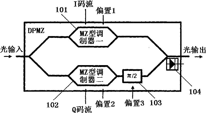
[0038] In order to improve the control accuracy of the bias voltage of the two MZ modulators and the phase delayer in the DPMZ, and reduce the complexity and cost of the control circuit, an embodiment of the present invention provides a method and method for bias control of a dual-parallel MZ modulator. device.

[0039] The bias control method of the dual-parallel MZ modulator provided in the embodiment of the present invention includes the following steps:

[0040] A. Convert the photocurrent output by the dual-parallel MZ modulator DPMZ into a voltage signal. The voltage signal contains the low-frequency RF components of the I code stream and the Q code stream, and then divide the voltage signal into two channels for low-pass filtering and high-pass processing respectively. Filter processing to obtain the average light intensity of the DPMZ...


PUM


Abstract

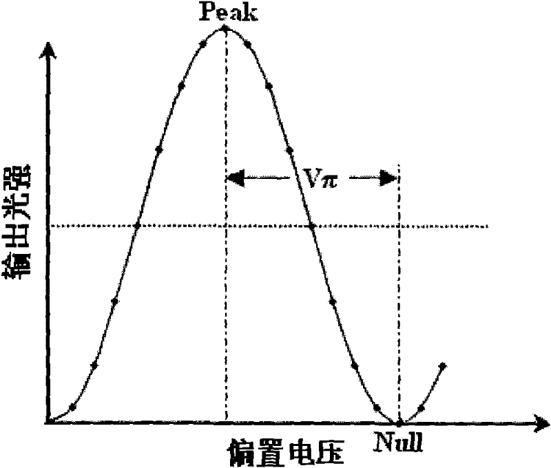
The invention discloses a method and device for offset control of a DPMZ (dual parallel Mach-Zehnder) modulator. The method comprises the following steps: converting a light current output by the DPMZ modulator into two paths of voltage signals, and carrying out LPF (Lowpass filtering) and highpass filtering to obtain the average light intensity output by the DPMZ and LF (low frequency) RF (radio frequency) components of the output light intensity; dividing time into continuous multiple groups of TSs (time slots), wherein each group of TSs comprises TS1, TS2 and TS3; controlling the bias 1 and bias 2 of two MZ modulators in the TS1 and the TS2 so as to obtain the maximum average light intensity output by the DPMZ modulator, thus the bias 1 and bias 2 are in an optimal state; adopting a logarithmic RF detector to detect power of the LF RF components of the light intensity output by the DPMZ modulator, representing the power in a DC (direct-current) voltage Vrf form; and changing phase delay by bias 3 of a control bit delayer in the TS3 so as to minimize the Vrf, thus the bias 3 is in an optimal state. The method and device are used to improve the bias control accuracy of the two MZ modulators and a phase delayer in the DPMZ modulator and reduce the complexity and the cost of a circuit.

Description

technical field [0001] The invention relates to the field of optical communication, in particular to a bias control method and device for a double-parallel MZ modulator. Background technique [0002] In the current optical communication field, the optical phase modulator represented by differential quadrature phase shift keying has become the mainstream product in the industry. In the differential quadrature phase shift keying modulation system, the most widely used modulator is DPMZ (Dual Parallel Mach-Zehnder modulator, dual parallel MZ modulator) made of lithium niobate material. Advanced modulation formats such as coherent dual-polarization quadrature phase-shift keying and orthogonal frequency division multiplexing currently being studied in the industry, as well as various advanced modulation formats in the future, will also use DPMZ as a modulator. Therefore, DPMZ has a wide range of applications both at present and in the future. However, due to the high sensitivit...

Claims


Application Information

Patent Timeline
Patent Type & Authority Applications(China)
IPC IPC(8): H04B10/155G02F1/01H04B10/54
Inventor 张璋杨宁李玲龙熙平陈德华
Owner FENGHUO COMM SCI & TECH CO LTD
Learn More