Method and system of resource position indication and channel blind detection, and apparatus thereof

A resource location and indication technology, which is applied to receiver-specific devices, transmission systems, digital transmission systems, etc., and can solve the problem of inability to know the CSS and UESS resource locations of PDCCHs.

Active Publication Date: 2011-09-28
DATANG MOBILE COMM EQUIP CO LTD
View PDF4 Cites 114 Cited by
  • Summary
  • Abstract
  • Description
  • Claims
  • Application Information

AI Technical Summary

Problems solved by technology

[0012] Embodiments of the present invention provide a resource location indication method and device, which are used to solve the problem that the terminal cannot know the resource location of CSS and UESS of PDCCH

Method used


Image

  • Method and system of resource position indication and channel blind detection, and apparatus thereof
  • Method and system of resource position indication and channel blind detection, and apparatus thereof
  • Method and system of resource position indication and channel blind detection, and apparatus thereof

Examples


Embodiment 1

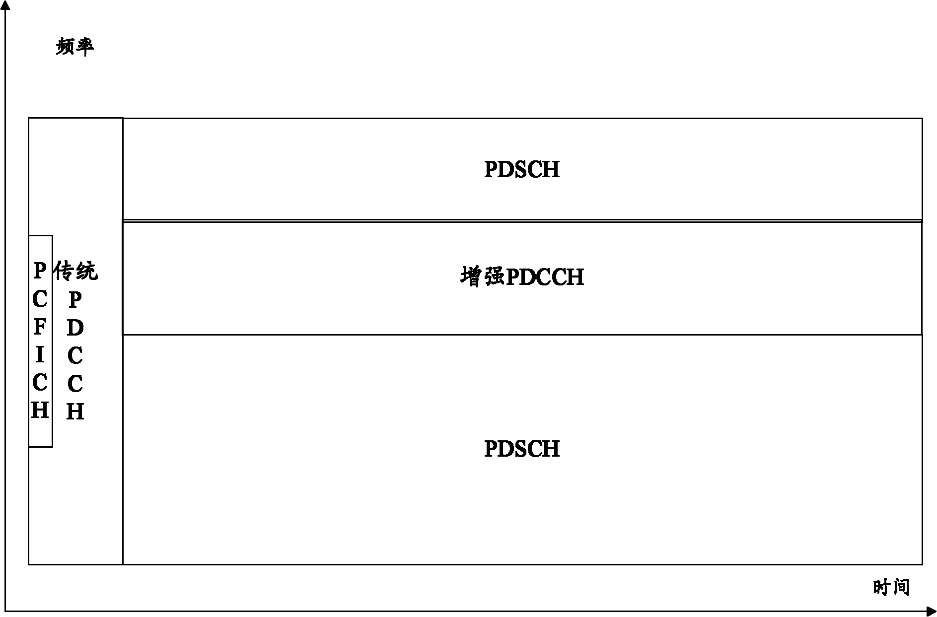
[0122] If the system uses RRH-based COMP technology or MU-MIMO technology and other applications that require higher PDCCH capacity, then since the UE in the Legacy PDCCH area can still receive signals correctly, the CSS resource of the UE that supports this solution can be allocated The location is configured in the Legacy PDCCH area, while the resource location of the UESS is configured in the enhanced PDCCH area, and all subframes within the effective time of the configuration adopt the same configuration. In this way, the extra system overhead occupied by repeatedly sending the DCI needed to schedule the common channel in the enhanced PDCCH region is avoided, and the efficiency of the system is improved.

Embodiment 2

[0124] If the system adopts the ABS-based TDM ICIC mechanism to support the interference avoidance of the layered network, since the performance of the Legacy PDCCH in the interfered cell cannot be guaranteed, the CSS of the UE supporting this solution in the interfered cell and The resource locations of the UESS are all configured in the enhanced PDCCH region, and all subframes use the same configuration during the effective configuration time. This improves PDCCH reception performance.

[0125] Here, the interfered cell refers to the cell of the interfered base station. For example, in the scenario of layered coverage of a macro base station and a pico base station, the macro base station is the interfered base station, and the pico base station is the interfered base station; in the layered coverage of the macro base station and the femto base station In the scenario, the femto base station is the interfering base station, and the macro base station is the interfered base s...

Embodiment 3

[0127] If the system adopts the TDM ICIC mechanism based on ABS to support the interference avoidance of the layered network, since the performance of the Legacy PDCCH in the interfered subframe in the interfered cell cannot be guaranteed, this scheme can be supported in the interfered cell The resource positions of the UESS and CSS in the interfered subframe of the UE are configured in the enhanced PDCCH area, and at the same time, the resource position of the CSS in the uninterferenced subframe of the above-mentioned UE can be configured in the Legacy PDCCH area, and the resource position of the UESS Configured in the enhanced or legacy PDCCH area. In this way, on the basis of ensuring the PDCCH receiving performance of the UE in the interfered cell, the extra system overhead occupied by DCI required for repeatedly sending and scheduling common channels in the enhanced PDCCH area is reduced as much as possible, and the system efficiency is improved.

[0128] Here, the interf...


PUM


Abstract

An embodiment of the invention discloses a method and a system of resource position indication and channel blind detection, and an apparatus thereof, which relate to the wireless communication technology field. Through using the method, a physical downlink control channel (PDCCH) can be correctly received by a terminal. In the invention, a base station sends resource position information of common search space (CSS) and UE-specific search space (UESS) of PDCCH to the terminal. Blind detection is performed by the terminal according to the resource positions of CSS and UESS of PDCCH.

Description

technical field [0001] The present invention relates to the field of wireless communication, in particular to a method, system and device for resource location indication and channel blind detection. Background technique [0002] In the Long Term Evolution (LTE) system, the Physical Downlink Control Channel (PDCCH) is sent in the control area of ​​each radio subframe, and forms a time-division multiplexing (TDM) system with the Physical Downlink Shared Channel (PDSCH) for transmitting downlink data. relationship, such as figure 1 shown. PDCCH is sent through the first N orthogonal frequency division multiplexing (OFDM) symbols in a downlink subframe, where N may be 1, 2, 3 or 4, and N=4 is only allowed to appear when the system bandwidth is 1.4 MHz system. [0003] The control region for transmitting PDCCH in the LTE system is composed of logically divided control channel elements (CCEs), where the mapping from CCEs to resource elements (REs) adopts a completely interleav...

Claims


Application Information

Patent Timeline
Patent Type & Authority Applications(China)
IPC IPC(8): H04W24/00H04W72/04H04W72/12
CPCH04L5/0037H04L5/0091H04L1/0038H04L5/0053H04L1/00H04B17/00H04B7/2603H04J11/00
Inventor 潘学明赵锐肖国军沈祖康
Owner DATANG MOBILE COMM EQUIP CO LTD
Why Eureka
Try Eureka