Apparatus for fixing a switching device on stock rails of a switch

A technology of switch conversion and basic rail, which is applied to the mechanical equipment, track, road and other directions used to operate the switch or line interrupter, and can solve the problems of the position deviation of the basic rail and the inability to ensure the stability of the support.

Inactive Publication Date: 2011-09-28
VAE火车系统有限责任公司 +1
View PDF1 Cites 2 Cited by
  • Summary
  • Abstract
  • Description
  • Claims
  • Application Information

AI Technical Summary

Problems solved by technology

When the basic rail is elastically supported on the fixed roadbed or on the sleeper, the inherent motion of the basic rail also includes the lateral overturning motion, which on the one h

Method used


Image

  • Apparatus for fixing a switching device on stock rails of a switch
  • Apparatus for fixing a switching device on stock rails of a switch
  • Apparatus for fixing a switching device on stock rails of a switch

Examples


Embodiment Construction

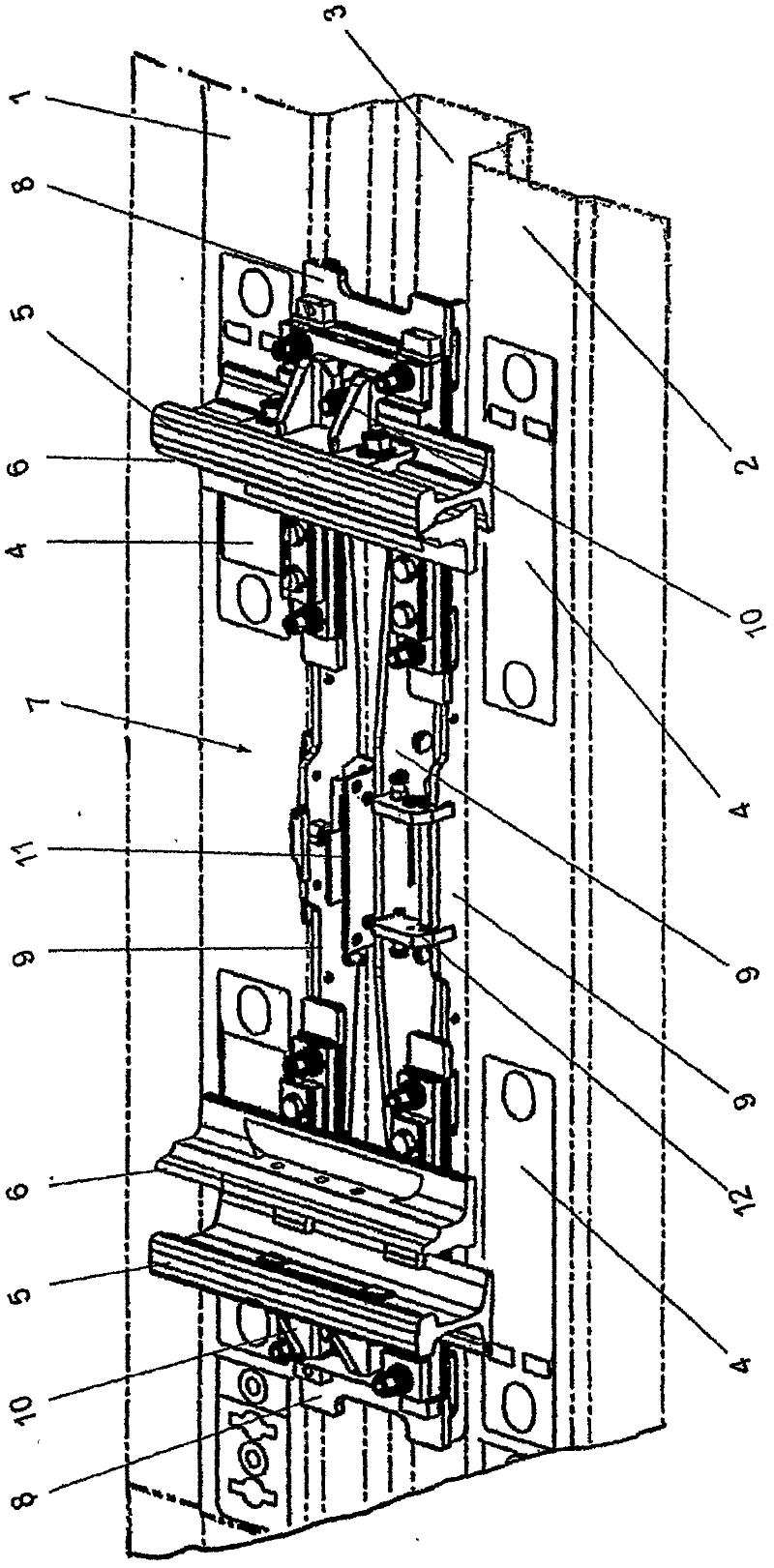
[0017] figure 1 The sleeper distance 3 between the two schematically shown sleepers 1 and 2 is shown in . On the sleepers 1 and 2 , the schematically shown backing plates or webs 4 of the rails 5 can likewise be seen, wherein, for the sake of clarity, only the basic rails are shown in the region of the sleeper spacing 3 . In addition, the switch rails 6 can be seen, the switch rail 6 shown on the right resting against the base rail 5 , the switch rail 6 shown on the left facing away from the base rail 5 .

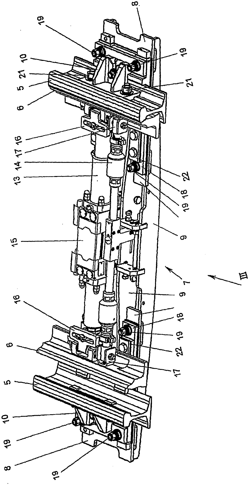
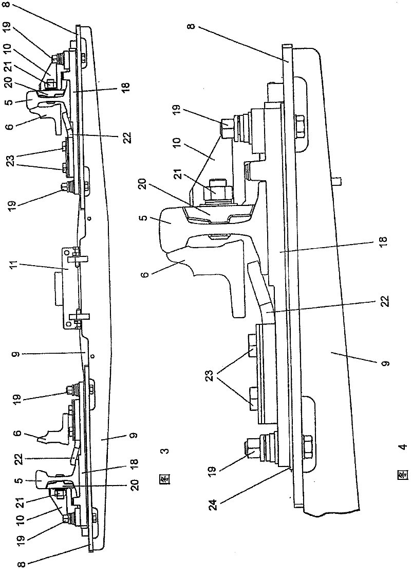
[0018] Furthermore, a frame 7 is provided, which consists of a carrier plate 8 and three webs 9 connecting the carrier plate. Fastening elements 10 , which surround the rail base on the outside, are each screwed to the support plate 8 , with which fastening elements the frame 7 is fastened to the web waist of the basic rail 5 . exist figure 1 It can also be seen that the web 9 has a fastening device 11 for the drive of the track transition and a fastening device 12 for t...


PUM


Abstract

In an apparatus for fixing a switching device (13) on stock rails (5) of a switch, comprising a mounting for the switching device that can be fixed on the stock rails (5), the mounting is formed by a rigid frame (7) which is designed to be connected transversely to the rail longitudinal direction of the two stock rails (5) and fixed to the rail stem of the stock rails (5).

Description

technical field [0001] The invention relates to a device for fastening a switch switch to a base rail of a switch, comprising a fastening device for the switch switch which can be fastened to the base rail. Background technique [0002] Such a device is known, for example, from DE 200 10 922 U1. [0003] The drive unit of the switch switch is usually formed by a hydraulic or electromagnetic drive, which is arranged rigidly in the housing between the base rails or, if appropriate, can also be arranged outside the base rails of the switch and via the adjusting rod (Stellstange) Connect with switch point rail. In conventional switch switching devices, the housing of the drive unit is fastened on the track sleeper or in a trogschwell by means of a correspondingly designed fastening element. [0004] In order to provide switch switching devices with which the switch switch rails can be adjusted with greater precision between the approaching and further away positions, it has be...

Claims


Application Information

Patent Timeline
IPC IPC(8): B61L5/02
CPCB61L5/02E01B7/06E01B2205/00
Inventor M·沃尔夫H·阿赫莱特纳R·宽奇尼希
Owner VAE火车系统有限责任公司
Why Eureka
Try Eureka