
Hydraulic control system in working machine

A technology for hydraulic control and work machinery, which is applied to fluid pressure actuation system components, mechanical equipment, earth movers/shovels, etc. Reduced discharge flow rate, stable supply flow rate, and easy operation

Inactive Publication Date: 2014-04-09
CATEPILLAR SARL
View PDF9 Cites 2 Cited by
  • Summary
  • Abstract
  • Description
  • Claims
  • Application Information

AI Technical Summary

Problems solved by technology

Furthermore, there is a problem that the operating speed of the hydraulic actuator increases or decreases due to the increase or decrease of the combined flow rate from the accumulator to the discharge path of the hydraulic pump, which is the problem to be solved by the present invention.

Method used


Image

  • Hydraulic control system in working machine
  • Hydraulic control system in working machine
  • Hydraulic control system in working machine

Examples


Embodiment Construction

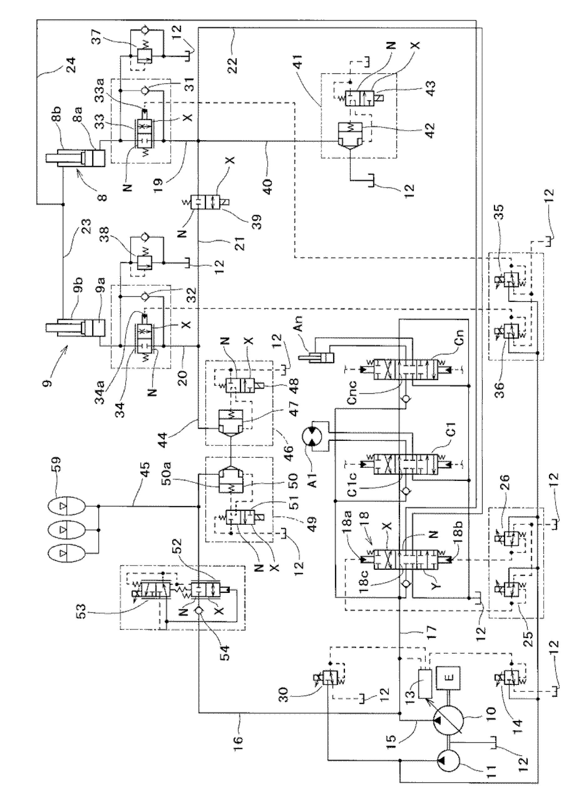
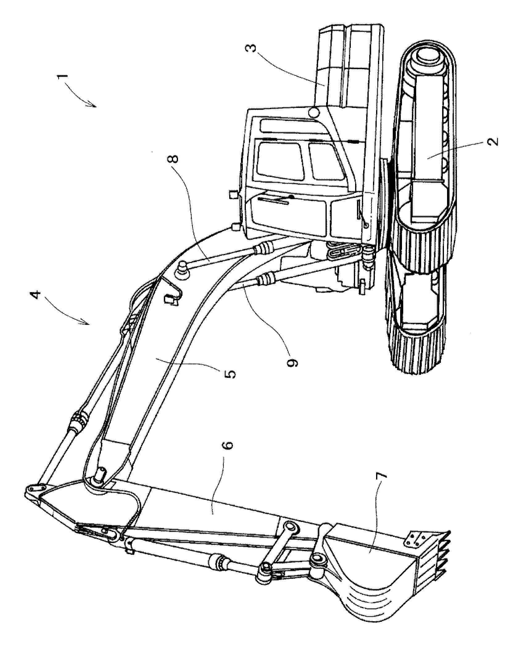
[0019] Embodiments of the present invention will be described below based on the drawings. exist figure 1 Among them, 1 is a hydraulic excavator as an example of a working machine. This hydraulic excavator 1 is composed of a crawler-type lower traveling body 2, an upper revolving body 3 rotatably supported above the lower traveling body 2, and The work section 4 installed in front of the upper swing body 3 is composed of various parts, and further, the work section 4 is supported by the boom 5 which is vertically swingable at the base end of the upper swing body 3 , and is freely swingable back and forth. An arm 6 at the front end of the boom 5 , a bucket 7 attached to the front end of the arm 6 , and the like are configured.

[0020] Furthermore, 8 and 9 are a pair of left and right first and second boom cylinders for swinging the above-mentioned boom 5 up and down, and these first and second boom cylinders 8 and 9 are constituted as follows: The pressure of 9a maintains t...


PUM


Abstract

A hydraulic control system in a working machine, configured such that hydraulic energy of oil discharged from a hydraulic actuator is stored as pressure into an accumulator and such that the pressurized oil stored in the accumulator is converged into oil discharged from a hydraulic pump, wherein the pressurized oil in the accumulator is adapted to be efficiently used without waste. A control device (27) obtains the actuator supply flow rate (Qc) to be supplied to a hydraulic actuator based on the amount of operation of a hydraulic actuator operating device and on the discharge pressure (Pp) of a main pump (10) and controls the discharge flow rate (Qp) of the main pump (10) and an accumulator flow rate (Qa) so that the actuator supply flow rate (Qc) is the sum of the discharge flow rate (Qp) of the main pump (10) and the accumulator flow rate (Qa).

Description

technical field [0001] The present invention belongs to the technical field of hydraulic control systems for working machines capable of recovering and reusing hydraulic energy contained in oil discharged from a hydraulic actuator. Background technique [0002] In general, among working machines, there are working machines such as hydraulic excavators equipped with a plurality of hydraulic actuators for supplying pressure oil from a hydraulic pump. However, in the hydraulic circuit of such working machines, conventional The oil discharged from the hydraulic actuator is returned to the oil tank. For example, in a hydraulic excavator, when the boom cylinder is reduced to lower the working part, the oil discharged from the head side oil chamber of the boom cylinder returns to the oil tank, and at this time, the boom cylinder head side The oil in the oil chamber becomes high pressure due to the weight of the front working part, and has high oil pressure energy. If the high oil ...

Claims


Application Information

Patent Timeline
Patent Type & Authority Patents(China)
IPC IPC(8): F15B21/14E02F9/22F15B11/00
CPCF15B2211/88E02F9/2217F15B2211/413F15B2211/428F15B2211/212F15B2211/46E02F9/2296F15B2211/473F15B21/14F15B2211/41527F15B1/02E02F9/2285F15B2211/20523E02F9/2235
Inventor 和田笃志白仁启介井口高志
Owner CATEPILLAR SARL
Learn More