Tensioning device and method for applying prestressing force on high bending moment prestressed concrete electric pole

A tensioning device and prestressing technology, which is applied in the processing of building materials, construction, building construction, etc., can solve problems such as safety accidents, production safety accidents, steel plate ring deformation, etc., to ensure construction quality, facilitate assembly and construction, Ease of use

Active Publication Date: 2011-10-05
CHANGSHA SHENGFENG POLE MFG
View PDF7 Cites 6 Cited by
  • Summary
  • Abstract
  • Description
  • Claims
  • Application Information

AI Technical Summary

Problems solved by technology

However, at present, the tensioning process and devices for producing prestressed poles with ordinary bending moments cannot meet the prestressing requirements of prestressed poles with large bending moments.
Since the current tensioning process of applying prestress is external tension and external fixation, that is, outer arc ribs are set on the steel ring, and the outer arc ribs are used to apply force to the steel ring, and then the steel bars anchored on the steel ring are stretched. However, if it is stretched with a large tonnage exceeding the tension specified by ordinary electric poles, it will cause deformation of the steel plate ring, which is very prone to production safety accidents, and ultimately makes the existing stretching methods unable to safely and effectively produce large bending moment prestress. Concrete poles, and the existing tensioning tooling equipment is bulky and heavy, and the tension transmission of the jack that generates tension is in the form of pins. Under large-tonnage tension, the pins are subjected to greater shear force than the original process, resulting in deformation of the pins. , easily lead to safety accidents

Method used


Image

  • Tensioning device and method for applying prestressing force on high bending moment prestressed concrete electric pole
  • Tensioning device and method for applying prestressing force on high bending moment prestressed concrete electric pole

Examples


Embodiment Construction

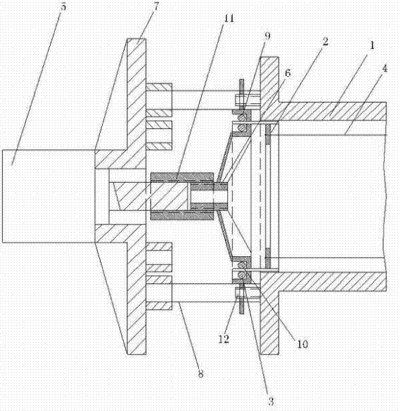
[0021] see figure 1 , the present invention includes a hollow steel mold 1 with an open end and a flange plate on the outside of the port, a steel ring 2, an outer arc rib 3 fixed on the outer wall of the steel ring 2, a steel bar 4 anchored on the steel ring 2, Jack 5, tension claw 6, support frame 7, fixed plate 9 inner arc rib 10 and tension nut, steel plate ring 2 and steel bar 4 are arranged inside steel mold 1 and steel plate ring 2 is fixed with outer arc rib 3 and protrudes To the outside of the steel mold 1, the support frame 7 is set on the jack 5, and the middle part of the support frame 7 is provided with a through hole for the pull shaft of the jack 5 to pass through, and the pull shaft of the jack 5 passes through the through hole of the support frame 7 and extends to the support On the other end of the frame 7, the tension claw 6 is connected to the pull shaft of the jack 5 through a tension nut 11 threaded, and the support frame 7 withstands the flange plate of...


PUM


Abstract

The invention discloses a tensioning device and method for applying a prestressing force to a high bending moment prestressed concrete electric pole. A pull shaft of a jack is connected with a tensioning claw by virtue of a tensioning nut in a screwing way, the claw hook of the tensioning claw is inserted into a steel plate coil to hook an inner arc rib, a steel bar anchored on the steel plate coil is tensioned, and the tension stress of prestressed steel is maintained by adopting an external fixation method that an adjusting screw rod of a fixed disk is screwed down to be against the end part of a steel mould. The invention has the technical effects that: the tensioning claw is adopted to hook the inner arc rib in the steel plate coil, thus tensioning is realized; the moment arm between the tensioning claw and the prestressed steel is small, thus the produced bending moment is low; and the steel plate coil does not deform under a tensile force of large tonnage, and the tensioning nutis adopted to connect the tensioning claw and the pull shaft of the jack in the screwing way, thus the technical problem that a bolt can not bear a shear force of large tonnage when the original boltis used for fixing is solved. The screw rod of the fixed disk is adopted for carrying out external fixation, thus the process is simple and convenient. The supporting lug of a supporting frame is of movable type, thus being applicable to production of various high bending moment electric holes in different specifications.

Description

technical field [0001] The invention relates to a tensioning device and method for applying prestress to a large bending moment prestress concrete pole. Background technique [0002] With the widespread use of large bending moment prestressed concrete poles, in order to improve the crack resistance of the poles, it is necessary to increase the tensile tonnage of prestressing the steel bars of the poles. However, at present, the tensioning process and devices used to produce prestressed electric poles with common bending moments cannot meet the prestressing requirements of prestressed electric poles with large bending moments. Since the current tensioning process of applying prestress is external tension and external fixation, that is, outer arc ribs are set on the steel ring, and the outer arc ribs are used to apply force to the steel ring, and then the steel bars anchored on the steel ring are stretched. However, if it is stretched with a large tonnage exceeding the tensio...

Claims


Application Information

Patent Timeline
Patent Type & Authority Applications(China)
IPC IPC(8): E04G21/12
Inventor 谌英武刘继章
Owner CHANGSHA SHENGFENG POLE MFG
Why Eureka
Try Eureka