Lighting fixture

A technology for lighting appliances and appliances, applied in lighting devices, fixed lighting devices, lighting auxiliary devices, etc., can solve the problems of disconnection, damage, diffusion, etc., and achieve the effect of improving heat dissipation effect and sufficient heat dissipation space

Inactive Publication Date: 2011-10-05
PANASONIC CORP
View PDF6 Cites 5 Cited by
  • Summary
  • Abstract
  • Description
  • Claims
  • Application Information

AI Technical Summary

Problems solved by technology

[0009] However, if there is a distance between the LED and the entrance, the light from the LED will diffuse before reaching the entrance, and the amount of light passing through the entrance will decrease, resulting in insufficient lighting effects.
[0010] In addition, in the above-mentioned lighting fixtures in which the lighting device is rotatably connected to the lamp, if the rotation range of the lighting device relative to the lamp is too large, the following problems are likely to occur during arrangement: the wires connecting the lighting device and the lamp body are Breakage caused by excessive bending, or damage caused by excessive movement of the lighting device relative to the lamp body, etc.

Method used


Image

  • Lighting fixture
  • Lighting fixture
  • Lighting fixture

Examples


Embodiment approach 1

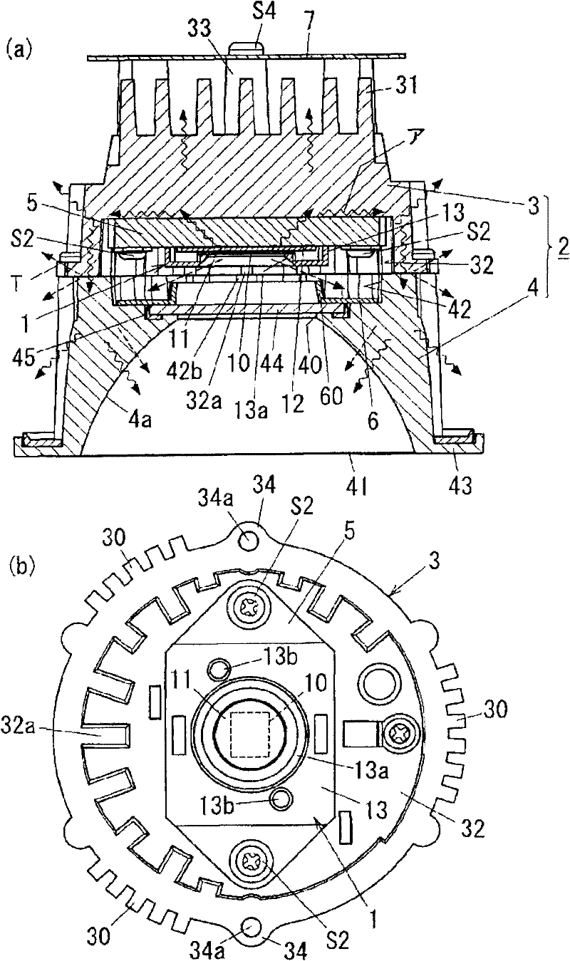
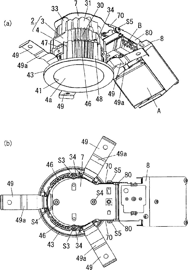
[0038] Next, embodiments of the lighting fixture of the present invention will be described with reference to the drawings. This embodiment is a lighting fixture embedded in the ceiling, such as figure 1 As shown in (a) and (b), an LED module 1 having a substrate 12 on which an LED chip 10 (light emitting diode) is mounted, and a bottomed cylindrical device body 2 formed by combining a base 3 and a frame 4 are provided. Additionally, if figure 2 As shown in (a) and (b), it is equipped with: a lighting device A that provides lighting power to the LED chip 10; The AC power of the power supply is transferred to the terminal block B of the lighting device A. In addition, since the lighting device A and the terminal block B are conventionally known, a detailed description thereof will be omitted here.

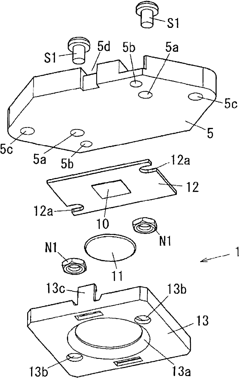
[0039] LED module 1, as shown in FIG. The sealing member 11 and the substrate 12 on which the LED chip 10 is mounted. In addition, a square cover 13 made of a resin material t...


PUM


Abstract

The invention provides a lighting fixture, which is characterized in that the lighting fixture comprises a light-emitting diode (LED); a lighting device for providing lighting electricity to the LED; and a bottom cylindrical fixture main body made of heat radiation materials and at least receiving the LED. The fixture main body further comprises an entrance port for light from the LED to enter and an exit port for the light entered from the entrance port to shine outwards. The fixture main body is such a part that the bottom of the inside is provided with the LED; and the heat sent out by the LED is dispersed outwards through the fixture main body itself. The entrance port is closed by a translucent part made of translucent materials. A heat radiation space for the heat sent out by the LED to be dispersed outwards through the fixture main body is equipped between the LED and the entrance port. The inner wall of the heat radiation space is provided with radiating fins.

Description

technical field [0001] The invention relates to a lighting appliance using light-emitting elements such as light-emitting diodes as light sources. Background technique [0002] Conventionally, downlights (lighting fixtures) using light-emitting diodes (hereinafter referred to as “LEDs”) embedded in ceilings as light sources, such as the downlight disclosed in Patent Document 1, are known. The downlight described in Patent Document 1 has a metal device main body, a light source board on which a plurality of LEDs are mounted, a power supply device for controlling the current required for lighting the LEDs, and a reflector and a shade for distributing light from the LEDs. . The light source substrate is mounted in contact with the bottom wall of the device main body. Furthermore, by dissipating the heat generated by the LED when it is turned on in the air via the light source substrate and the device main body, it is possible to prevent an increase in the ambient temperature ...

Claims


Application Information

Patent Timeline
Patent Type & Authority Applications(China)
IPC IPC(8): F21S8/02F21V29/00F21V7/00F21V17/10F21Y101/02F21V29/70F21Y115/10
CPCF21V21/04F21V23/02F21S8/02F21V23/023F21V23/026
Inventor 山口俊治
Owner PANASONIC CORP
Why Eureka
Try Eureka