
Data stream transmitting method and device

A data stream transmission and data technology, which is applied in the field of data transmission, can solve the problems of affecting the accuracy of uniform transmission and the large number of hardware resources, so as to achieve the effect of improving accuracy and reducing hardware resources

Active Publication Date: 2011-10-05
北京瀚景锦河科技有限公司
View PDF2 Cites 1 Cited by
  • Summary
  • Abstract
  • Description
  • Claims
  • Application Information

AI Technical Summary

Problems solved by technology

[0028] It can be seen that although typical transmission mode 1 and typical transmission mode 2 can achieve uniform speed transmission, typical transmission mode 1 adopts a rounding method when calculating the sending time of each data, which will affect the accuracy of uniform speed transmission, while In typical transmission mode 2, after the parameters are obtained by calculating formulas (1) and (3) by DSP or CPU, FPGA / ASIC needs to generate more counters (the number of counters varies with the transmission code rate), occupying hardware more resources

Method used


Image

  • Data stream transmitting method and device
  • Data stream transmitting method and device
  • Data stream transmitting method and device

Examples


Embodiment 1

[0078] In this embodiment, it is assumed that the given clock frequency is 27 MHz, the data line is 8 bits, and a code stream with a code rate of 4.8 Mbytes / s is to be transmitted. Assume that the precision of the integer part X is m=16, and the precision of the fractional part Y is n=16.

[0079] Calculated according to formula (1) to get t=27M / 4.8M=5.625;

[0080] Converted to binary:

[0081] X=0b 0000_0000_0000_0101, Y=0b 1010_0000_0000_0000

[0082] In the formula, 0b represents a binary number, and "_" has no special meaning, just for convenience of viewing, such as 0b0000_0000_0000_0101 and 0b 0000000000000101 are exactly the same.

[0083] For the convenience of expression, the clocks after the waiting state enters the working state are numbered. The current clock cycle is marked as Clk0, the first clock cycle after that is marked as Clk1, and the second clock cycle is marked as Clk1. . The i-th clock cycle is recorded as Clki.

[0084] In waiting state:

[0085] ...

Embodiment 2

[0102] In this embodiment, it is assumed that the given clock frequency is 27 MHz, the data line is 8 bits, and a code stream with a code rate of 8.9 Mbytes / s is to be transmitted. Assume that the precision of the integer part X is m=16, and the precision of the fractional part Y is n=16.

[0103] Calculated according to formula (1)

[0104] t=27M / 8.9M=3.0337078651685393258426966292135

[0105] Since the integer is 3 and m=16,

[0106] Therefore X = 0b 0000_0000_0000_0011,

[0107] Since the decimal is 0.0337078651685393258426966292135 and m=16

[0108] So to convert small to 16-bit binary:

[0109] 0.0337078651685393258426966292135*2 16 =2209.0786516853932584269662921348

[0110] Rounded to get 2209 into binary 0b 0000_1000_1010_0001

[0111] Y=0b 0000_1000_1010_0001

[0112] Other parameters can be obtained according to X and Y. The calculation method has been explained above. According to the calculation results, it can be known that there is at least 2 clock cycles...


PUM


Abstract

The invention discloses a data stream transmitting method comprising the steps of dividing every byte data holding time t into a bigit integral part X and a bigit decimal part Y, accumulating a numerical value of Y by an accumulator after one datum is sent out, and determining a clock interval of sending the next data according to the highest carry bit indentifier S accumulated by the accumulator. The invention also correspondingly discloses a data stream transmitting device. Through the invention, the decimal part can be maintained to control the data stream transmission when every byte data holding time is a nonnegative integer, thus the constant speed transmitting precision can be enhanced. Only one counter is needed in the invention, therefore, fewer resources on hardware are occupied.

Description

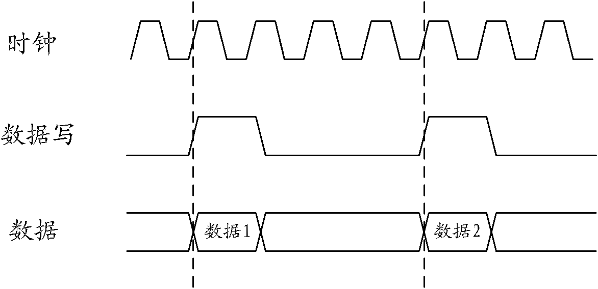
technical field [0001] The present invention relates to the technical field of data transmission, in particular to a method and device for data stream transmission. Background technique [0002] At present, synchronous transmission is widely used in data transmission. figure 1 It is a schematic diagram of the principle of synchronous transmission mode, such as figure 1 As shown, the interface signals of the sending end and the receiving end include clock, data write, and data signals. There can be multiple or only one data signal, and only one other signal. All signals are sent by the sending end. The timing of the synchronous transmission interface is as follows: figure 2 As shown, the receiving end samples the data write signal on the falling edge of each clock, and if the data write is high, the current data is received. figure 2 Among them, data 1 and data 2 are valid data, and other data are not valid data. [0003] For some occasions such as audio and video transm...

Claims


Application Information

Patent Timeline
Patent Type & Authority Applications(China)
IPC IPC(8): H04L7/00
Inventor 王万亭徐昕邵冬英呼大明郑海鸥于天歌
Owner 北京瀚景锦河科技有限公司
Learn More