Device and method for limiting the rail potential in a DC railway

A track and railway technology, applied in emergency protection circuit devices for limiting overcurrent/overvoltage, along the running track devices, circuit devices, etc., can solve the problems of slow response and high cost of switchgear, and achieve the effect of simple devices

Inactive Publication Date: 2011-10-05
SIEMENS AG
View PDF4 Cites 6 Cited by
  • Summary
  • Abstract
  • Description
  • Claims
  • Application Information

AI Technical Summary

Problems solved by technology

[0004] Since conventional switching devices react too slowly, it has hitherto been necessary to construct the switching device with cost-intensive and expensive components such as thyristors

Method used


Image

  • Device and method for limiting the rail potential in a DC railway
  • Device and method for limiting the rail potential in a DC railway

Examples


Embodiment Construction

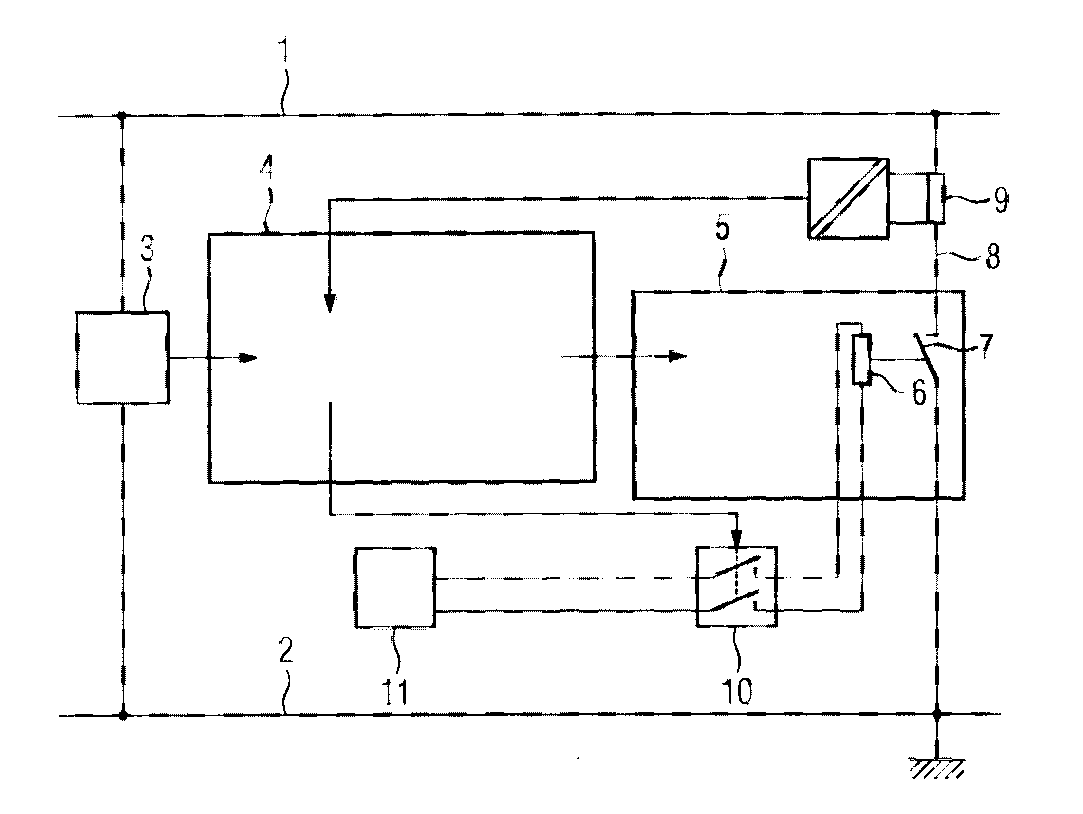
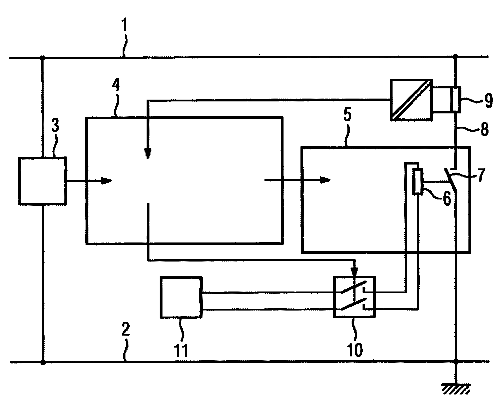
[0016] The voltmeter 3 is located between the track 1 of the DC railway and the building ground 2. The voltmeter 3 is connected to the de-energizing unit 5 of the contactor coil 6 via the dynamic control unit 4. As long as the contactor coil 6 passes current, it is kept at The switching device 7 on the connecting line 8 between the track 1 and the building ground 2 is opened. The contactor coil 6 works like an electromagnet here. The measured voltage can be compared with a threshold value in the voltmeter 3, and as soon as the voltmeter 3 confirms an excessive voltage, the contactor coil 6 is switched to no current via the control unit 4 and the de-energizing unit 5 in order to close the switching device 7, for example by mechanical springs. Undesirable track potentials can then flow from the track 1 via the connecting line 8 to the construction site 2 . The ammeter 9 is located on the connection line 8 , and the ammeter 9 is connected to the relay 10 via the control unit 4 ...


PUM


Abstract

The invention relates to a device and a method for limiting the rail potential in a DC railway, a low-impedance link (8) being arranged between the rail (1) and the ground (2) below the structure. A switchgear (7) which is connected to a control unit (4) via a control line is connected to the link (8), while the control unit (4) is connected to a voltmeter (3) that is arranged between the rail (1) and the ground (2) below the structure. According to the invention, the switchgear (7) comprises a contactor coil (6) that is connected to a dynamic control unit (4). The switchgear (7) closes and thus connects the link (8) in a conducting manner when the voltage between the rail (1) and the ground (2) below the structure exceeds a threshold value.

Description

technical field [0001] The invention relates to a device for limiting track potential in direct current railways, wherein a low-impedance connecting line is arranged between the track and the building ground, and wherein a switching device is inserted in the connecting line, the switching device It is connected via a control line to a control unit, which is connected to a voltmeter provided between the track and the building ground. [0002] The invention also relates to a method for limiting track potential using such a device in direct current railways. Background technique [0003] In direct current railways, the track potential must not exceed a predetermined maximum value in order to ensure that touching the track is not dangerous for people. Proposals have therefore been made to make the connection from the track to the building ground if the track potential is too high. For this, mechanical switching devices, so-called short-circuiters, are used, which have to meet ...

Claims


Application Information

Patent Timeline
Patent Type & Authority Applications(China)
IPC IPC(8): B60M5/02
CPCH02H3/14B60M5/02H02H9/041
Inventor 格德.海因乔格.库德里夫斯基亚历山大.肖姆伯格
Owner SIEMENS AG
Why Eureka
Try Eureka