Fiber bundle with pieced part, process for producing same, and process for producing carbon fiber
A manufacturing method and fiber bundle technology, which are applied in the field of carbon fiber manufacturing, can solve problems such as good productivity, and achieve the effects of improving productivity, good heat removal, and suppressing heat storage
- Summary
- Abstract
- Description
- Claims
- Application Information
AI Technical Summary
Problems solved by technology
Method used
Image

Examples
Embodiment 1
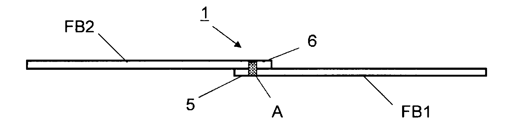
[0153] The end portion 5 of the first precursor fiber bundle FB1 and the end portion 6 of the second precursor fiber bundle FB2 were superposed so that the length of the fiber bundle superimposed portion was 400 mm. use Figure 5 In the splicing device shown, two fiber bundles are joined at the fiber bundle overlapping portion. At this time, three fiber interlacing devices 51 were used. The hole diameters of the fluid injection holes in the first fluid injection hole array 71 and the second fluid injection hole array 72 of each fiber interlacing device 51 were set to 1.5 mm, and the array pitch of the fluid injection holes was set to 2.5 mm. The length (column interval) L between the two fluid ejection hole rows 71, 72 in the fiber bundle longitudinal direction was set to 30 mm. The first and second fiber bundles FB1 and FB2 that were superimposed were given a slack of 9.0% by the fiber bundle relaxing device 53 using a round bar.
[0154] Thereafter, pressurized air at a p...
Embodiment 2
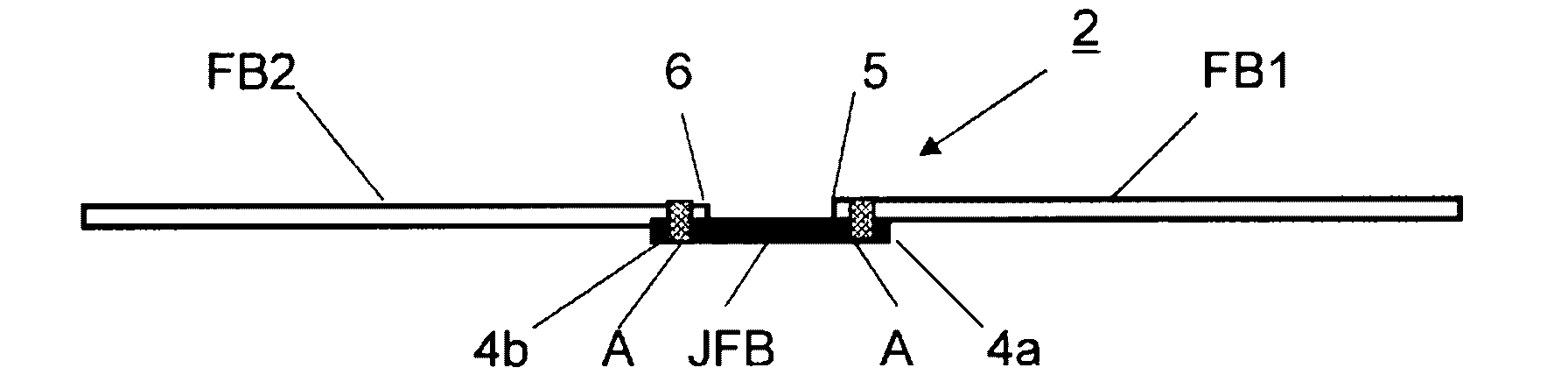
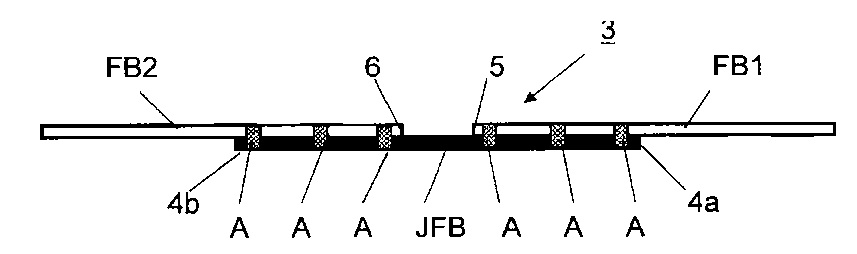
[0158] The same fiber bundles as in Example 1 were prepared for the first precursor fiber bundle FB1 and the second precursor fiber bundle FB2. Separately, a connecting fiber bundle JFB composed of a carbon fiber bundle having a filament count of 24,000 and a thermal conductivity of 55 W / m·K was prepared. Fold the prepared 3 fiber bundles into image 3 status shown. The length of the overlapping portion of the first precursor fiber bundle FB1 and the carbon fiber bundle JFB and the length of the overlapping portion of the second precursor fiber bundle FB1 and the carbon fiber bundle JFB were each set to 400 mm. The distance between the end of the first precursor fiber bundle FB1 and the end of the second precursor fiber bundle FB2 was set to 500 mm.
[0159] use Figure 5 In the jointing device shown, the first precursor fiber bundle FB1 is joined to the carbon fiber bundle JFB at each fiber bundle overlapping portion, and the second precursor fiber bundle FB1 is joined to ...
Embodiment 3
[0172] A space is left between the first precursor fiber bundle FB1 and the second precursor fiber bundle FB2, and carbon fibers serving as connecting fiber bundles JFB with the number of filaments of 48,000, 24,000, and 12,000 are laminated at the facing ends. The bundles were spliced to prepare three types of fiber bundle samples having spliced portions. At this time, when joining the superimposed fiber bundles, first, a slack of 9.0% is given to the superimposed fiber bundles in the longitudinal direction, and then, in order to join the two fiber bundles at the superimposed portion, use 3 fiber interweaving devices 51. Each fiber interlacing device 51 has a first fluid injection hole row 71 and a second fluid injection hole row 72 . Pressurized air at a pressure of 0.4 MPa was injected for 2 seconds from the fluid injection holes arranged at intervals in the respective fluid injection hole arrays to intertwine the plurality of fibers forming the fiber bundles at the re...
PUM
| Property | Measurement | Unit |
|---|---|---|
| length | aaaaa | aaaaa |
| length | aaaaa | aaaaa |
| density | aaaaa | aaaaa |
Abstract
Description
Claims
Application Information
 - R&D
- Intellectual Property
- Life Sciences
- Materials
- Tech Scout
- Unparalleled Data Quality
- Higher Quality Content
- 60% Fewer Hallucinations
Browse by: Latest US Patents, China's latest patents, Technical Efficacy Thesaurus, Application Domain, Technology Topic, Popular Technical Reports.
© 2025 PatSnap. All rights reserved.Legal|Privacy policy|Modern Slavery Act Transparency Statement|Sitemap|About US| Contact US: help@patsnap.com