Optical head device and method of manufacturing optical head device

An optical head and laser technology, applied in the manufacture of optical heads, optical recording heads, etc., can solve problems such as wavelength variation, deformation, and influence of optical system parts of emitted light, and achieve the effects of suppressing characteristic changes, improving durability, and high installation accuracy

Inactive Publication Date: 2007-01-10
SANKYO SEIKI MFG CO LTD
View PDF1 Cites 0 Cited by
  • Summary
  • Abstract
  • Description
  • Claims
  • Application Information

AI Technical Summary

Problems solved by technology

[0006] However, such a frame-type laser light-emitting element has the problem of being difficult to press-fit and fix on the light-emitting element holder and mount it on the base.
That is, if the outer shape is a cylindrical laser light-emitting element, although it is easy to be pressed into the round hole of the light-emitting element holder, in the case of a frame-type laser light-emitting element, it is necessary to place the lead frame with a square shape. If it is pressed into the hole of the rectangular section of the light-emitting element holder, excessive force will be applied to the square lead frame, so it is not easy
In addition, in the frame-type laser light-emitting element, since the square lead frame is formed of a thin plate, it may be deformed when it is forcibly pressed in. This deformation will cause the laser light-emitting element to be attached to the light-emitting element holder Accuracy drops
[0007] On the other hand, in the light-emitting element holder, the hole with a rectangular cross-section for pressing the frame-type laser light-emitting element is a deep and thin groove, and it is difficult to manufacture a mold that can form such a groove.
Therefore, the light emitting element holder cannot be easily produced using a mold
[0008] In addition, from the viewpoint of cost reduction, the thermal conductivity of the base formed of resin is low, and the heat generated by the frame-type laser light emitting element cannot be dissipated.
In addition, the extension parts on both sides of the lead frame are pushed by the leaf spring made of copper beryllium, so the heat generated by the frame-type laser light emitting element can be dissipated to the leaf spring, but its volume is very small, and there is no The problem of adequate cooling
Therefore, when the frame-type laser light-emitting element is used for a long period of time, the frame-type laser light-emitting element will store heat and be at a high temperature, and there will be problems such as fluctuations in the wavelength of emitted light and increased power consumption.
In addition, there is a problem that the life of the laser light-emitting element in the frame is significantly reduced due to the long use time at high temperature.
In addition, when the optical system parts are arranged near the frame-type laser light-emitting element, the optical system parts will be adversely affected, so the optical parts must be separated from the frame-type laser light-emitting element, and there is a problem of increasing the size of the optical head device.

Method used


Image

  • Optical head device and method of manufacturing optical head device
  • Optical head device and method of manufacturing optical head device
  • Optical head device and method of manufacturing optical head device

Examples


Embodiment Construction

[0030] Next, an optical head device to which the present invention is applied will be described with reference to the accompanying drawings.

[0031] (the whole frame)

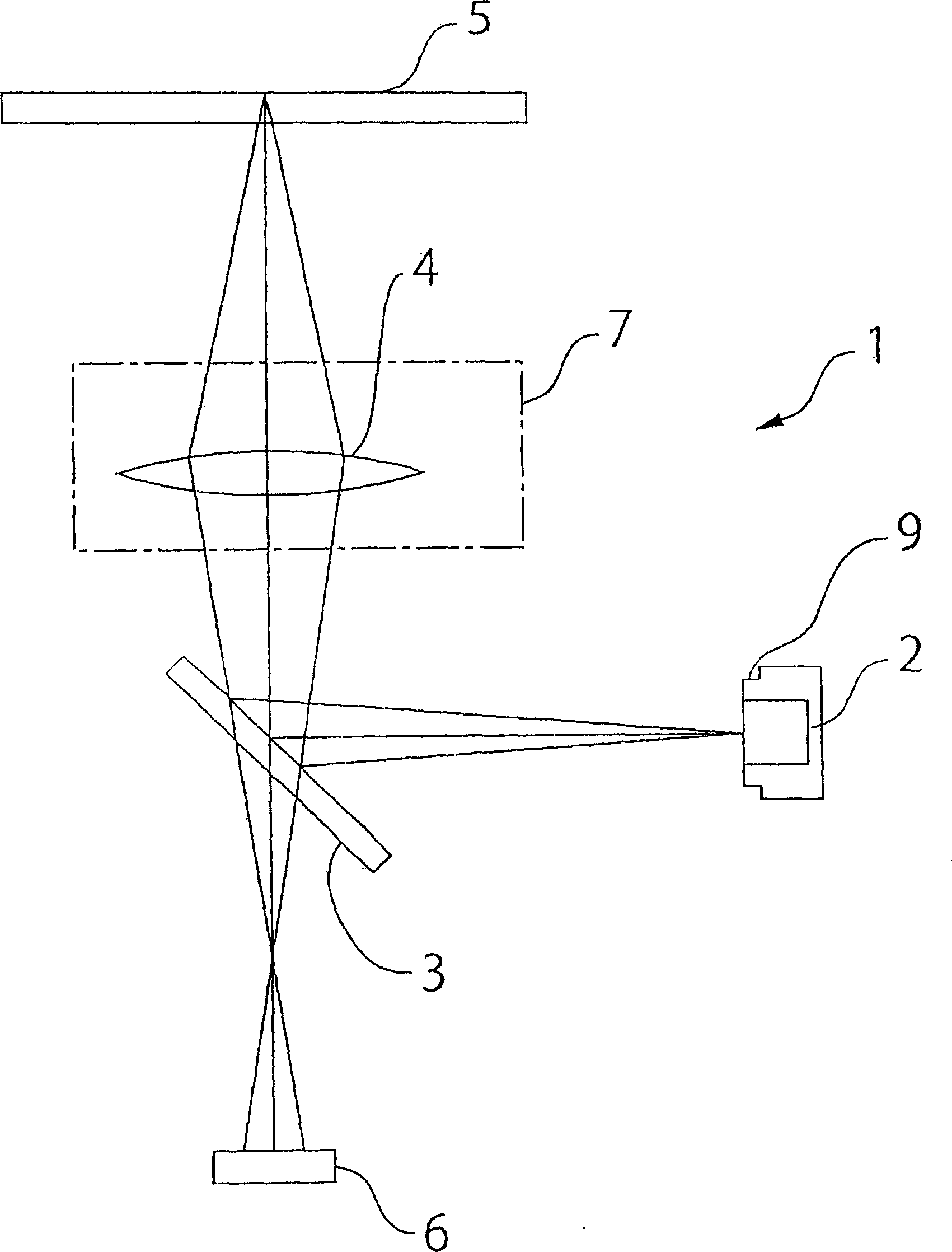
[0032] figure 1 It is a schematic configuration diagram showing an example of an optical head device to which the present invention is applied.

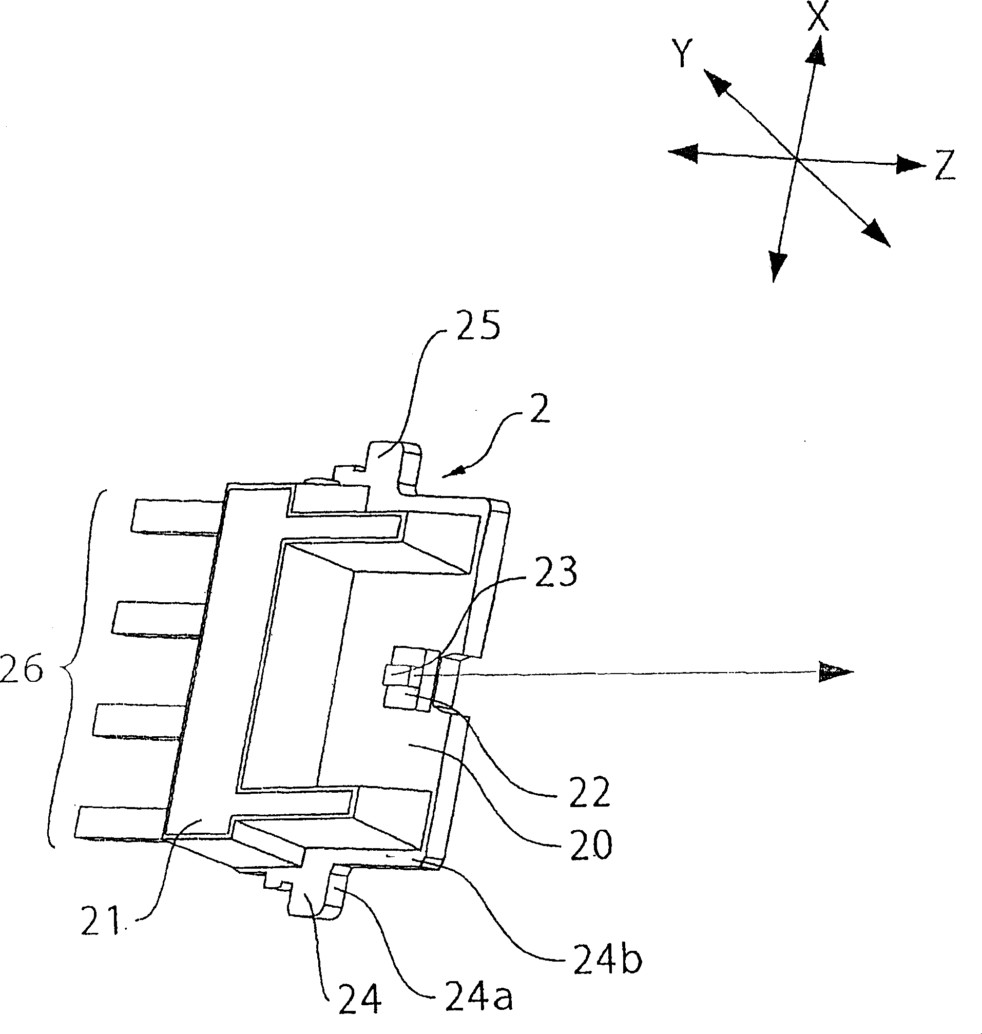
[0033] Such as figure 1 As shown, the optical head device 1 is a device for recording and reproducing information on an optical recording medium 5 such as a CD or DVD, and has: a laser light emitting element 2; Lens 3; the objective lens 4 that focuses the laser light reflected by the half mirror 3 on the optical recording medium 5; the photodetector 6 that receives the return light reflected by the optical recording medium 5 and passes through the objective lens 4 and the half mirror 3, these optical parts is mounted on base 10 (see Figure 7 )superior. In addition, an objective lens driving mechanism 7 for adjusting the position of the objective lens 4 in the ...


PUM


Abstract

Optical head device and its manufacturing method. A semiconductor laser chip mounted on a lead frame. The frame-type laser photo emitter molded of resin is mounted onto a base together with optical components escept the side of the semiconductor laser chip. A photo emitter holder is provided for mounting the photo emitter on the base. The photo emitter holder has mounting portions for mounting the laser photo emitter and a notch that is cut out in a direction orthogonal to an optical axis of light emitted by the semiconductor laser chip for mounting the laser photo emitter onto the mounting portions. The laser photo emitter is fixed to the notch by an adhesive.

Description

technical field [0001] The present invention relates to an optical head device used for reproducing optical recording media such as CDs and DVDs, and a method of manufacturing the optical head device. More specifically, it relates to a mounting technique for mounting a frame-type laser light emitting element on a base. Background technique [0002] The optical head device used for reproducing optical recording media such as CD and DVD has: a laser light-emitting element; an objective lens that focuses the laser light emitted from the laser light-emitting element on the optical recording medium, and drives the objective lens in the focusing direction and tracking direction. Mechanism; a light-receiving element that receives the reflected light reflected by the optical recording medium; an optical system part that guides the laser between the laser light-emitting element and the light-receiving element. These optical components are mounted on a base. [0003] Here, conventio...

Claims


Application Information

Patent Timeline
Patent Type & Authority Applications(China)
IPC IPC(8): G11B7/12G11B7/22
Inventor 浅川新六武居勇一
Owner SANKYO SEIKI MFG CO LTD
Why Eureka
Try Eureka