Battery charging device and method
A battery charging and battery technology, applied in battery circuit devices, circuit devices, secondary battery charging/discharging, etc., can solve problems such as ion concentration differences, and achieve the goals of suppressing the increase of internal resistance, prolonging battery life, and shortening charging time Effect
- Summary
- Abstract
- Description
- Claims
- Application Information
AI Technical Summary
Problems solved by technology
Method used
Image

Examples
Embodiment 1
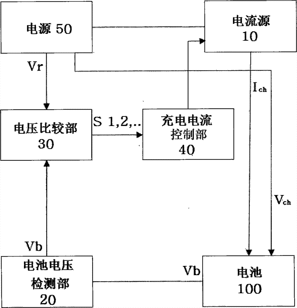
[0042] figure 1 It is a schematic structural block diagram of the battery charging device according to Embodiment 1 of the present invention.
[0043] The battery charging device of the present invention includes: a current source 10 that generates a charging current for charging a battery; a battery voltage detection unit 20 that detects the battery voltage of the battery 100 that is charged by the charging current Ich supplied from the current source. The terminal voltage Vb; the voltage comparison unit 30, comparing the battery voltage (battery terminal voltage) Vb increased with the supply of the charging current and the preset standard voltage Vr; the charging current control unit 40, if the comparison result of the voltage comparison unit 30 is When the battery voltage Vb matches the standard voltage Vr, the charging current Ich supplied from the current source to the battery is controlled; In addition, the above-mentioned and following configurations of the battery ch...
Embodiment 2
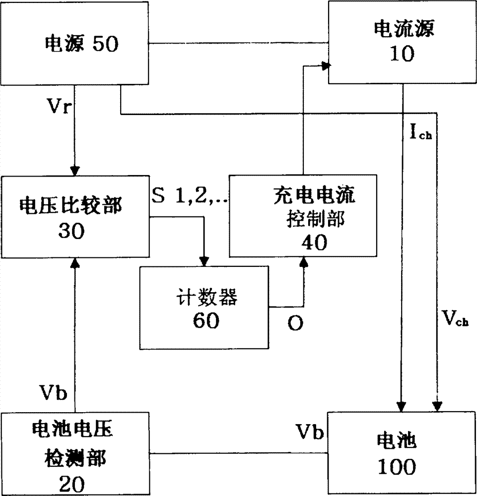
[0076] image 3 It is a schematic structural block diagram of the battery charging device of Embodiment 2 of the present invention, and the battery charging device of Embodiment 2 also includes calculating the signal S (=Vb=Vr=S1, S2, ...) counter 60 of the number.
[0077] Here, the counter 60 may transmit the constant current charging stop signal O to the charging current control unit 40 when, for example, the generation number of the signal S exceeds a predetermined number (set value). With the transmission of the constant current charging stop signal O, the charging current control unit 40 supplies the current Ich4 from the current source 10 to the battery. In addition, the stop signal O is transmitted to the device control unit, and the device control unit receiving the stop signal O controls the power supply 50 to apply a constant charging voltage to the battery.
[0078] In addition, in the image 3 In the illustrated embodiment, when the count value of the counter 6...
Embodiment 3
[0080] Figure 4 It is a schematic structural block diagram of a battery charging device according to Embodiment 3 of the present invention, and the battery charging device according to Embodiment 3 also includes a display device (charging confirming part) which can be realized by using LEDs and the like, which blinks according to the constant current charging stop signal from the above-mentioned counter. )70.
[0081] Since the above-mentioned display device 70 is also provided, the user of the battery charging device can accurately confirm the charging status of the battery 100 through the flickering of the above-mentioned LED.
[0082] In addition, the signals transmitted from the counter 60 to the display device 70 may include the above-mentioned S1 to Sn signals in addition to the above-mentioned stop signal O, and the above-mentioned display device 70 can be blinked with the transmission of the above-mentioned signals S1 to Sn.
[0083] Therefore, the user of the chargi...
PUM
 Abstract
Description
Claims
Application Information
 - R&D
- Intellectual Property
- Life Sciences
- Materials
- Tech Scout
- Unparalleled Data Quality
- Higher Quality Content
- 60% Fewer Hallucinations
Browse by: Latest US Patents, China's latest patents, Technical Efficacy Thesaurus, Application Domain, Technology Topic, Popular Technical Reports.
© 2025 PatSnap. All rights reserved.Legal|Privacy policy|Modern Slavery Act Transparency Statement|Sitemap|About US| Contact US: help@patsnap.com