Method and device for calibrating longitudinal welding seam of steel pipe
A correction method and steel pipe technology, which are applied in the field of electro-hydraulic correction methods and their devices, can solve problems such as inability to meet fast and accurate corrections, non-compliance with working position requirements, etc.
- Summary
- Abstract
- Description
- Claims
- Application Information
AI Technical Summary
Problems solved by technology
Method used
Image

Examples
Embodiment 1
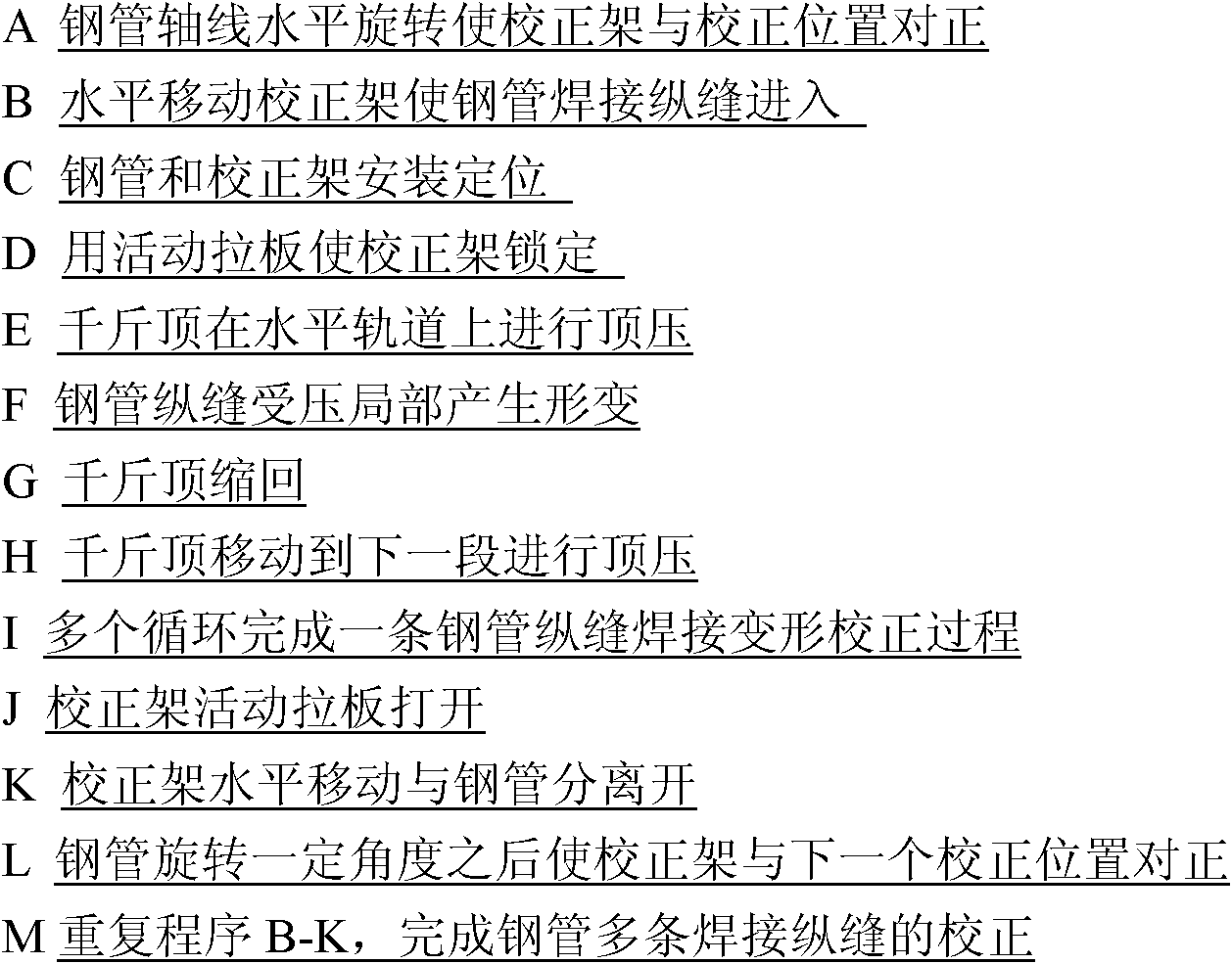
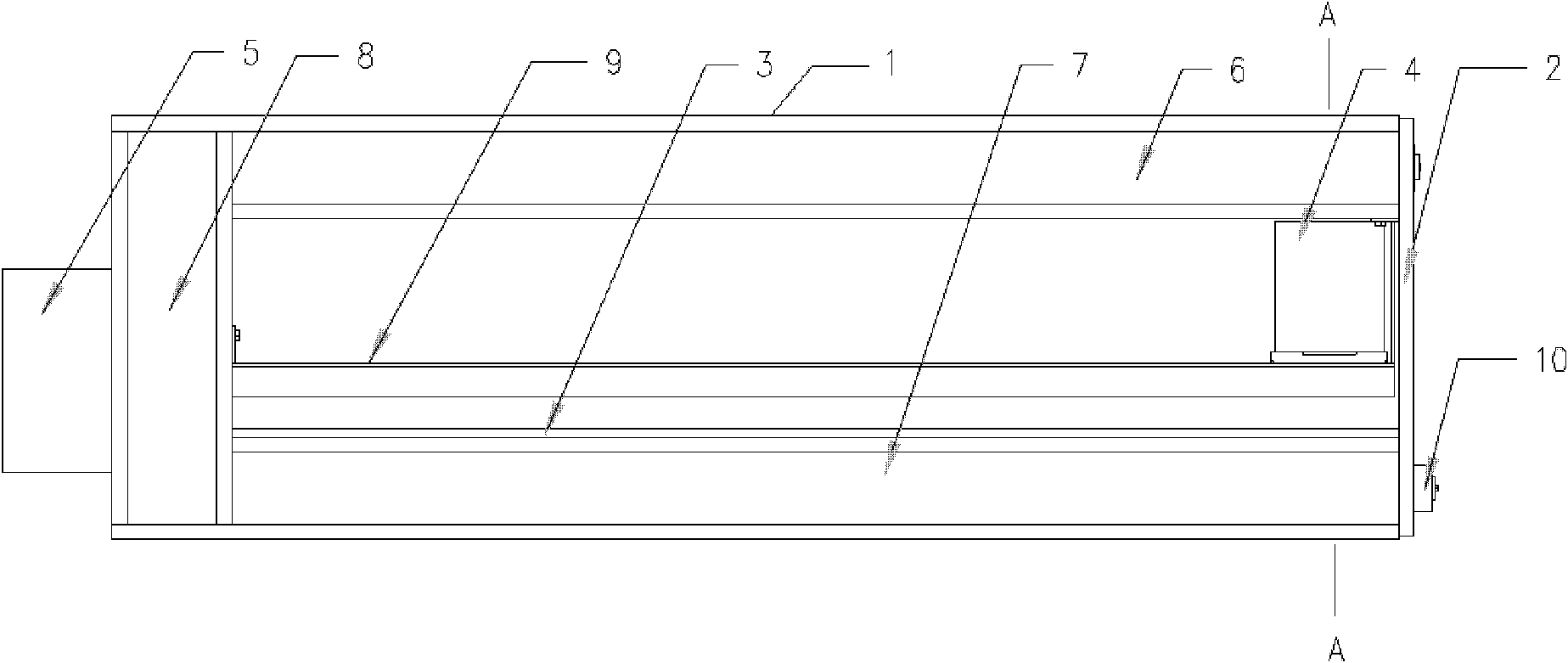
[0013] Embodiment 1: as figure 1 A correction frame shown is composed of a horizontally placed U-shaped frame 1, a movable pull plate 2, an adjustment backing plate 3, a hydraulic jack 4 and an electric pump station 5 thereof. The U-shaped frame includes an upper beam 6, a lower beam 7, a column 8 and a horizontal track 9. The top surface of the lower beam 7 is a concave groove, and the open end of the U-shaped frame has a pin shaft 10 connected to a movable pull plate, and the pin shaft 10 For fixed or telescopic type, the telescopic pin is installed in the pin hole 11 of the beam, and the hydraulic jack 4 is installed between the upper beam 6 and the lower beam 7 of the U-shaped frame 1, and its horizontal track 9 As a support and can move longitudinally, the hydraulic jack 4 is a manual mode, and the hydraulic jack 4 and the electric pump station 5 are split structures. The movable pull plate 2 is installed on the open end of the U-shaped frame 1. There are two pin holes o...
Embodiment 2
[0015] Embodiment 2: as Figure 5 A correction frame shown is composed of a horizontally placed U-shaped frame 1, a movable pull plate 2, an adjustment backing plate 3, a hydraulic jack 4 and an electric pump station 5 thereof. The U-shaped frame includes an upper beam 6, a lower beam 7, a column 8 and a horizontal track 9. The top surface of the lower beam 7 is a concave groove, and the open end of the U-shaped frame has a pin shaft 10 connected to a movable pull plate, and the pin shaft 10 It is fixed or telescopic, the telescopic pin is installed in the pin hole 11 of the beam, the hydraulic jack 4 is installed between the upper beam and the lower beam of the U-shaped frame 1, and its horizontal track 9 is used as a support And can move longitudinally, the movement of the hydraulic jack 4 can be driven by the electric screw nut 12 or the trolley driven by the motor reduction gear, the movable pull plate 2 is installed on the open end of the U-shaped frame 1, and the movable...
Embodiment 3
[0017] Embodiment 3: as Figure 4 A calibration frame with an automatic calibration procedure shown is composed of a horizontally placed U-shaped frame 1 , a movable pull plate 2 , an adjustment backing plate 3 , a hydraulic jack 4 and its electric pump station 5 . The U-shaped frame includes an upper beam 6, a lower beam 7, a column 8 and a horizontal track 9. The top surface of the lower beam 7 is a concave groove, and the open end of the U-shaped frame has a pin shaft 10 connected to a movable pull plate, and the pin shaft 10 It is fixed or telescopic, the telescopic pin is installed in the pin hole 11 of the beam, the hydraulic jack 4 is installed between the upper beam and the lower beam of the U-shaped frame 1, and its horizontal track 9 is used as a support And can move vertically, the movement of the hydraulic jack 4 is driven by the electric screw nut 12 or the trolley driven by the motor reduction gear, the movable pull plate 2 is installed on the open end of the U-s...
PUM
 Abstract
Description
Claims
Application Information
 - R&D
- Intellectual Property
- Life Sciences
- Materials
- Tech Scout
- Unparalleled Data Quality
- Higher Quality Content
- 60% Fewer Hallucinations
Browse by: Latest US Patents, China's latest patents, Technical Efficacy Thesaurus, Application Domain, Technology Topic, Popular Technical Reports.
© 2025 PatSnap. All rights reserved.Legal|Privacy policy|Modern Slavery Act Transparency Statement|Sitemap|About US| Contact US: help@patsnap.com