Hub lathe jig

A technology of lathe fixtures and hubs, applied in clamping, turning equipment, manufacturing tools, etc., can solve problems such as high equipment costs, rising production costs, and inconvenient clamping, so as to reduce production costs, reduce equipment costs, and ensure machining accuracy Effect

Inactive Publication Date: 2011-10-12
LIUZHOU CITY LONGCHEN AXLE PARTS MFG
View PDF0 Cites 22 Cited by
  • Summary
  • Abstract
  • Description
  • Claims
  • Application Information

AI Technical Summary

Problems solved by technology

[0002] The wheel hub is an important part of the car. It is very important to ensure the coaxiality of the bearing holes at both ends in the processing of the wheel hub. The clamping requirements for the hub are relatively high during processing. If the clamping does not meet the requirements, it will directly affect the machining accuracy of the hub. The overall size of the wheel hub is relatively large. It is inconvenient to clamp on a small horizontal lathe, and it is difficult to ensure the machining accuracy. Generally, the industry does not use a small horizontal lathe to process the wheel hub, but usually processes it on a vertical lathe or a large horizontal lathe. The price of wheel hubs, vertical lathes or large horizontal lathes is relatively high. Due to the high cost of equipment, the production cost of the enterprise has increased significantly, which is not conducive to improving the economic benefits of the enterprise.

Method used


Image

  • Hub lathe jig
  • Hub lathe jig
  • Hub lathe jig

Examples


Embodiment Construction

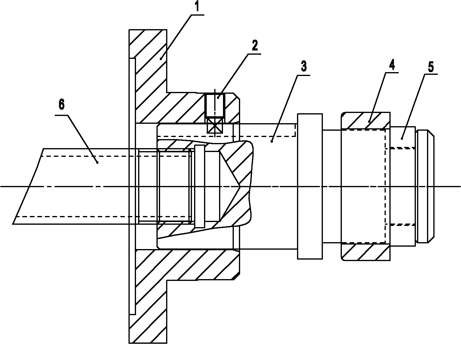
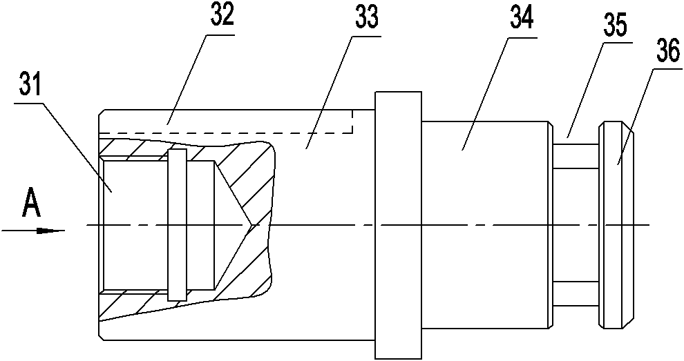
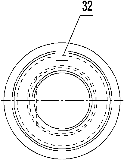
[0023] Such as Figure 1 to Figure 6 As shown, the hub lathe clamp of the present invention includes a positioning disc 1, a clamping slider 3, a support sleeve 4, a tension washer 5 and a pull tube 6, and the positioning disc 1 includes a ) on the main body 11 and one end of the protruding main body 11 is used to locate the positioning part 12 of the hub bearing hole 71, the positioning disc 1 is also provided with a through hole 14 that runs through the main body 11 and the positioning part 12, and the clamping slider 3 includes setting The connecting shaft 33 in the through hole 14 of the positioning disc 1 and the positioning shaft 34 connected to the end of the connecting shaft 33 away from the positioning disc 1, the end of the connecting shaft 33 is recessed inwardly to be provided with a connecting hole 31, and the positioning shaft 34 is close to the end of the free end. The inner depression forms an annular groove 35, and the free end of the positioning shaft 34 is t...


PUM


Abstract

The invention provides a hub lathe jig, relating to a jig for the field of machining. The hub lathe jig comprises a positioning disc, a clamping pull head, a supporting sleeve, a tensioning spacer and a pull tube, wherein the positioning disc comprises a main body part and a positioning part, wherein the main body part is connected to a lathe principal shaft, and the positioning part protrudes out of one end of the main body part to position a hub bearing hole; the clamping pull head comprises a connecting shaft and a positioning shaft, wherein the connecting shaft is arranged in a through hole of the positioning disc, the positioning shaft is connected to one end of the connecting shaft, which is far away from the positioning disc, the end part of the connecting shaft is inwards concavely provided with a connecting hole, the positioning shaft is inwards concavely provided with an annular groove near the tail position of a free end, and a protruded clamping part is formed at the outer side of the groove; the supporting sleeve is sleeved on the surface of an excircle positioned at the inner side of the annular groove of the positioning shaft, the outer surface of the supporting sleeve is matched with the inner surface of one of inner holes of a hub, and the end surface of the inner side of the supporting sleeve is clamped on the end surface of the inner side of the inner hole of the hub; the tensioning spacer is arranged in the annular groove and clamped with the end surface of the outer side of the supporting sleeve; one end of the pull tube is connected with the connecting hole of the connecting shaft of the clamping pull head, and the other end of the pull tube is connected with a hydraulic cylinder.

Description

technical field [0001] The invention relates to a fixture used in the field of mechanical processing, in particular to a lathe fixture for processing automobile wheel hubs. Background technique [0002] The wheel hub is an important part of the car. It is very important to ensure the coaxiality of the bearing holes at both ends in the processing of the wheel hub. The clamping requirements for the hub are relatively high during processing. If the clamping does not meet the requirements, it will directly affect the machining accuracy of the hub. The overall size of the wheel hub is relatively large. It is inconvenient to clamp on a small horizontal lathe, and it is difficult to ensure the machining accuracy. Generally, the industry does not use a small horizontal lathe to process the wheel hub, but usually processes it on a vertical lathe or a large horizontal lathe. The price of wheel hubs, vertical lathes or large horizontal lathes is relatively high. Due to the high cost of...

Claims


Application Information

Patent Timeline
Patent Type & Authority Applications(China)
IPC IPC(8): B23B5/02B23Q3/06
Inventor 朱志强
Owner LIUZHOU CITY LONGCHEN AXLE PARTS MFG
Why Eureka
Try Eureka