Workbench with multiple degrees of freedom

A workbench and degree of freedom technology, applied in the direction of workbench, manufacturing tools, metal processing equipment, etc., can solve the problems that the fixed structure of the workbench cannot be rotated, and the fixed structure of the workbench cannot be moved, etc., to achieve increased layout space and convenient layout Effect

Inactive Publication Date: 2011-10-12
许晓华
View PDF2 Cites 158 Cited by
  • Summary
  • Abstract
  • Description
  • Claims
  • Application Information

AI Technical Summary

Problems solved by technology

[0007] The invention solves the disadvantage that the workbench is a fixed structure and cannot be moved in the prior art, and provides a multi-degree-of-freedom workbench, which enables the workbench to move in any direction on the horizontal plane
[0008] The invention also solves the disadvantage that the workbench in the prior art is a fixed structure and cannot rotate, and provides a multi-degree-of-freedom workbench, so that the upper surface of the workbench can be tilted freely to achieve angle adjustment

Method used


Image

  • Workbench with multiple degrees of freedom
  • Workbench with multiple degrees of freedom
  • Workbench with multiple degrees of freedom

Examples


Embodiment 1

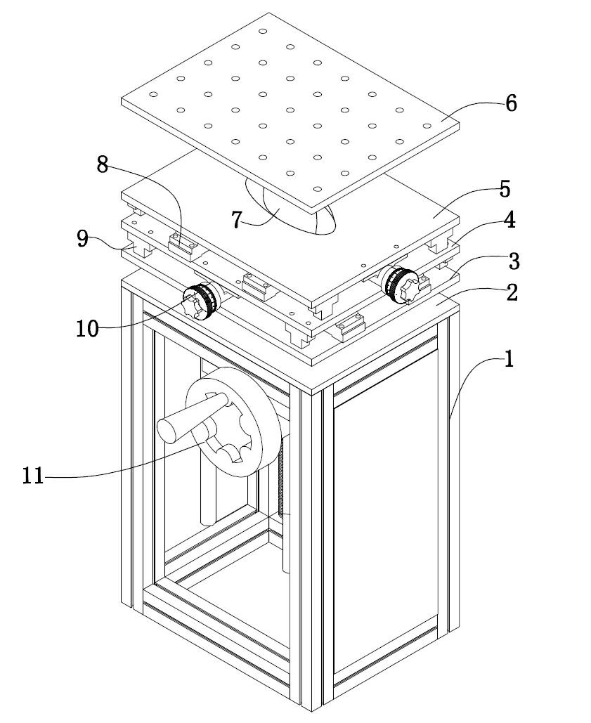
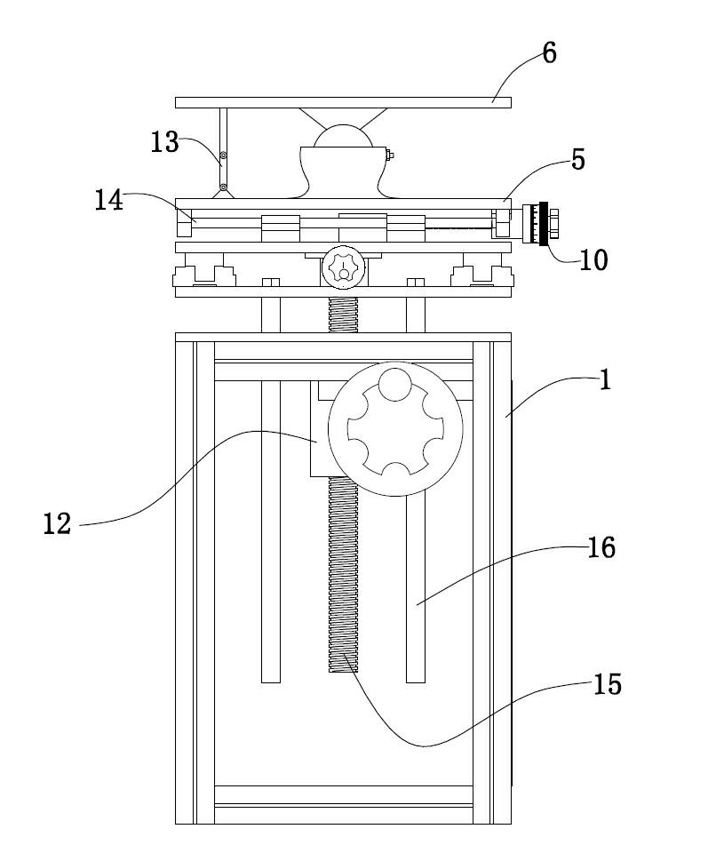
[0029] Embodiment 1: A kind of multi-degree-of-freedom workbench (see attached figure 1 attached figure 2 ), including a base 1 with a frame structure, a moving device arranged on the base and a workbench 6 connected with the movement device. The workbench is provided with a plurality of positioning holes, and the base is made of multiple square steel splicing. The upper surface of the support plate 2 is provided with a threaded hole and two light holes symmetrical to the threaded hole on the support plate. The moving device includes an up and down lifting mechanism, a moving mechanism on a horizontal plane and a multi-angle rotating mechanism. The up and down lifting mechanism includes The leading screw 15 arranged on the vertical support plate and the rotating sleeve 12 connected with the leading screw, the leading screw passes through the rotating sleeve, the rotating sleeve is provided with a gear with gear teeth, the center of the gear is provided with a threaded hole, a...

Embodiment 2

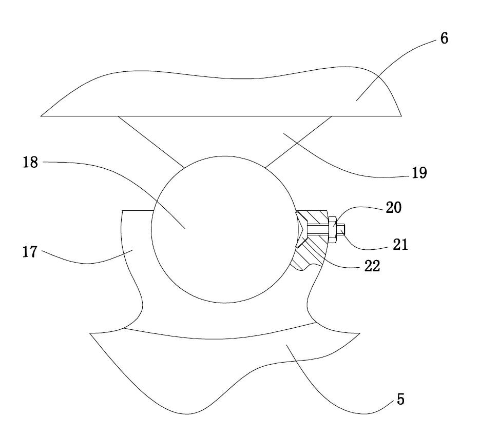
[0035] Embodiment 2: A kind of multi-degree-of-freedom workbench (see attached Figure 4 attached Figure 5 ), the universal connection device includes a universal joint, and the universal joint includes a cross shaft 25 in the middle and two U-shaped forks 24 arranged vertically. The other U-shaped fork is fixed to the center of the upper surface of the X-direction moving plate. Two vertical shaft ends of the cross shaft are provided with spline grooves, and the shaft ends are sleeved with tapered locking sleeves 23 (see attached Image 6 ), the inner hole of the locking sleeve is provided with a rib 27 corresponding to the spline groove, the outer surface of the locking sleeve is a tapered surface, and the end of the U-shaped fork corresponding to the shaft end is provided with a tapered hole 26 , the shaft end is provided with a thread on the outside, and a lock nut is screwed on the thread, the lock nut is in contact with the lock sleeve, the tapered surface of the lock ...


PUM


Abstract

The invention relates to a workbench with multiple degrees of freedom, which can move and rotate in multiple directions and is beneficial to overcoming of the disadvantage that the workbench in the prior art is of a fixed structure and can not move. The workbench comprises an elevator mechanism, a moving mechanism on a horizontal plane and a multi-angle rotating mechanism, wherein the elevator mechanism and the moving mechanism are of a lead screw moving mechanism, and the multi-angle rotating mechanism comprises a universal connection device and a locking mechanism. The moving mechanism can drive the workbench to move on the horizontal plane and ensure that the workbench can reach any positions on the horizontal plane within an effective range, and an X-directional moving mechanism and a Y-directional moving mechanism can operate independently or in a combined manner; the multi-angle rotating mechanism drives the surface of the workbench to incline; and the mechanisms are mutually combined to complete position change of the workbench surface.

Description

technical field [0001] The invention relates to a workbench structure, in particular to a multi-degree-of-freedom workbench capable of moving and rotating in multiple directions. Background technique [0002] General processing operations need to be equipped with a workbench, and some are more professional workbenches. A good and suitable workbench plays a very important role in promoting the work, which can improve the efficiency of processing, improve the accuracy and stability of operations, and at the same time It can also reduce the labor burden of the operator, which is more ergonomic. [0003] The existing workbenches are generally of fixed structure, and the position of the workbench will not change. To change the position of the workbench, it is necessary to move the base of the whole workbench, and change the position of the base to change the position of the workbench, but the work The base of the table is heavy, and it is not convenient to move. To move the work...

Claims


Application Information

Patent Timeline
Patent Type & Authority Applications(China)
IPC IPC(8): B25H1/02B23Q1/25
CPCB23Q1/25B23Q1/4857B23Q1/626B25H1/02B25H1/14
Inventor 孙祝兵
Owner 许晓华
Why Eureka
Try Eureka