Hydraulic drive unit for injection moulding machine

A technology of injection molding machine and driving unit, applied in the direction of fluid pressure actuating device, etc., can solve the problem of large space position of the displacement measurement system, and achieve the effect of saving cost

Active Publication Date: 2011-10-12
ENGEL AUSTRIA
View PDF5 Cites 2 Cited by
  • Summary
  • Abstract
  • Description
  • Claims
  • Application Information

AI Technical Summary

Problems solved by technology

[0006] The disadvantage of these hydraulic drive units is that the displacement measuring system takes up a relatively large space in the a...

Method used


Image

  • Hydraulic drive unit for injection moulding machine
  • Hydraulic drive unit for injection moulding machine
  • Hydraulic drive unit for injection moulding machine

Examples


Embodiment Construction

[0025] It should be noted that the following functional descriptions are all aimed at the core-pulling mechanism of the injection molding machine, which is only used as an example here, because general functions can be used for all movements of the hydraulic transmission components of the injection molding machine.

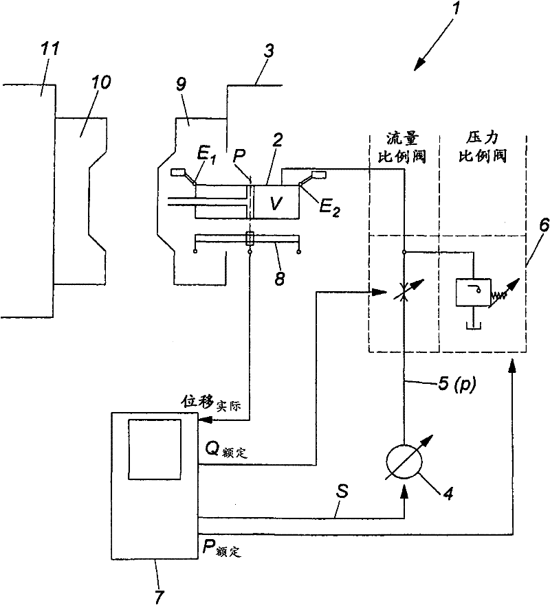
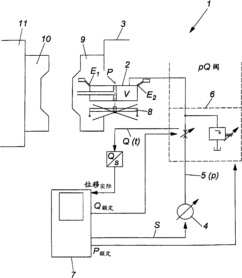
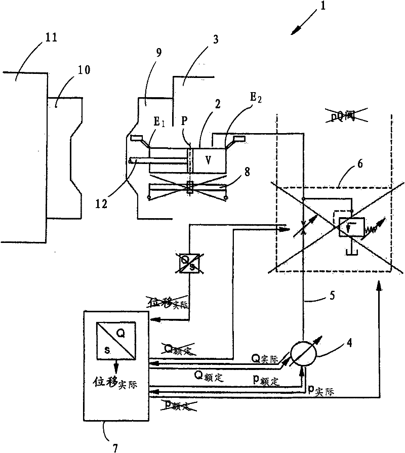
[0026] Generally speaking, the hydraulic drive unit 1 can move, for example, the core-pulling mechanism in the area of ​​the fixed mold clamping plate 3 through the piston of the hydraulic cylinder 2 . The mold half 9 is arranged on the fixed mold jaw 3 , where a second mold half 10 can be moved towards the mold half 9 via the movable mold jaw 11 .

[0027] In a standard injection molding machine, the pressure and flow of the moving device (hydraulic cylinder 2 and piston) of the injection molding machine components are controlled by controlling the pump. In special circumstances (such as the attached figure 1 shown) using a pressure proportional valve. In this ...


PUM


Abstract

The invention provides a hydraulic power unit (1) for an injection molding machine, which comprises a piston for moving the components of an injection moulding machine and the piston can be in a hydraulic movement between two end positions (E1, E2) in a hydraulic cylinder (2); a hydraulic pump (4) for pumping hydraulic fluid; a hydraulic line (5) arranged between the hydraulic pump (4) and the hydraulic cylinder (2); and a control or regulating unit (7) for controlling or regulating the hydraulic pump (4). The flow rate (Q) of the hydraulic fluid per unit time (t) is measurable and a corresponding signal is transmitted to the control or regulation unit (7). The position (P) of the piston is calculated by the control or regulation unit (7).

Description

technical field [0001] The invention relates to a hydraulic drive unit for an injection molding machine, comprising: a hydraulically movable piston between two end positions in a hydraulic cylinder for moving a component of an injection molding machine; A hydraulic pump; a hydraulic line between the hydraulic pump and the hydraulic cylinder; and a control or regulation unit for controlling or regulating the hydraulic pump (and optionally a valve). The invention also relates to an injection molding machine equipped with such a hydraulic drive unit. Background technique [0002] Hydraulically driven movements are to be performed in the different areas or structural units of the injection molding machine. For example, drive units of this type are provided for core pullers (Kernzüge), ejectors (ejector rods), clamping plates (locking plates) and similar components, most of which use hydraulic oil to be delivered to certain hydraulic cylinders accordingly The way in the zone ma...

Claims


Application Information

Patent Timeline
IPC IPC(8): B29C45/82
CPCB29C45/82B29C45/67B29C45/76B29C2945/76056B29C2945/76083B29C2945/76096B29C2945/76307B29C2945/76498B29C2945/76785B29C2945/76866B29C2945/76896B29C2945/76946F15B15/2838
Inventor H·弗里茨A·洛纳克尔
Owner ENGEL AUSTRIA
Why Eureka
Try Eureka