Supercharge Your Innovation With Domain-Expert AI Agents!

Combined structure of flat blade wiper

A non-bracket type and bracket type technology is applied in the field of combined structure of non-bracket type wipers, which can solve the problems of reducing the competitive advantage of product market price, unfavorable mass production capacity, and rubber wiper jitter, etc. The effect of increasing mass production capacity and reducing power burden

Inactive Publication Date: 2011-10-12
东莞山多力汽车配件有限公司
View PDF24 Cites 2 Cited by
  • Summary
  • Abstract
  • Description
  • Claims
  • Application Information

AI Technical Summary

Problems solved by technology

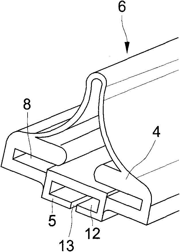
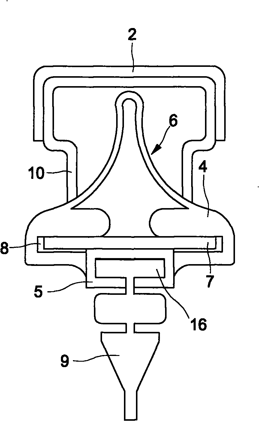
[0007] The main reason for the above-mentioned missing is that it does not directly transmit the force from the wiper rocker arm 2 from the rigid metal spine 7 to the rigid bottom support 5, but instead transmits the force from the rigid metal spine 7. The force is firstly used as an interface for power transmission through the soft upper support part 4, and then indirectly transmits the force to the hard bottom support part 5, so that the force transmission of each back and forth wiping , a short-term hysteresis will occur, and cause the rubber scraper 9 to vibrate on the windshield 3 of the car. Therefore, this bad structure, in addition to violating the design on the principle of mechanical transmission, also brings consumers Consequences of the above adverse effects
[0008] Furthermore, because the upper support part 4 is made of elastic soft material, the frictional resistance of the metal spine strip 7 when it is inserted into the assembly channel 8 is relatively large, so the assembling man-hours consumed will be more, which is not conducive to improving the quality. In addition to the production capacity of production, it will also lead to an increase in the overall assembly cost and reduce the competitive advantage of the market price of the product

Method used


Image

  • Combined structure of flat blade wiper
  • Combined structure of flat blade wiper
  • Combined structure of flat blade wiper

Examples


Embodiment Construction

[0129] see Figure 8 to Figure 11 , Figure 14 As shown in FIG. 20, a combined structure of a non-support type wiper according to the present invention includes:

[0130] A metal dome body 20, a flat rectangular strip made of flexible metal material, has a rectangular cross-section and two long sides 21 and two short sides 22 parallel to each other;

[0131] A receiving seat 30 is fixed on the central position of the metal shrapnel body 20. It is a rectangular parallelepiped formed by integral injection molding of plastic material. It has a top surface 31, a bottom surface 32, two long sides 33 and two short sides 34. The top surface 31 is convex Two vertical surfaces 35 parallel to each other are provided, and a support shaft 36 is straddled between the two vertical surfaces 35, which can be connected and fixed on the end of the wiper rocker arm 2 after a wiper connector A is mated ( As shown in Figure 20), in addition, between the two short sides 34, there is an accommodat...


PUM


Abstract

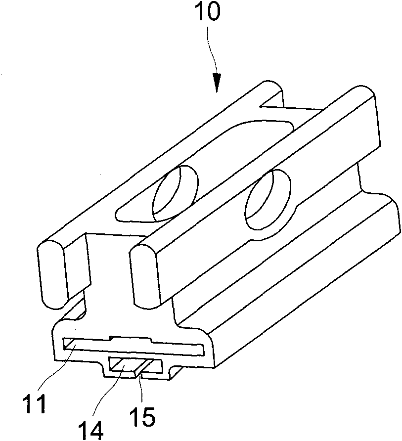
The invention provides a combined structure of a flat blade wiper, which comprises a metal elastic sheet body, a bearing seat, two clamping seat bodies, two outer protecting bushes and a strip blade, wherein the bearing seat and the two clamping seat bodies are respectively provided with an upper accommodating channel and a lower accommodating channel with the same section, and the upper sections of the metal elastic sheet body and the strip blade can be simultaneously inserted into the upper accommodating channel and a lower accommodating channel; when the wiper wipes water back and forth, the acting force generated by a wiper rocker can be directly transmitted to the two semirigid clamping seat bodies through the rigid metal elastic sheet body to synchronously drive the strip blade to wipe a windshield of an automobile, so that delay or a temporarily paused shaking phenomenon cannot occur in the whole process of transmitting the acting force of the wiping action; therefore, the tranquility in the automobile cannot be broken, the power load of the wiper rocker is reduced, the service life of the strip blade can be prolonged, and the replacement cost can be reduced.

Description

【Technical field】 [0001] The invention relates to a combined structure of a non-support type wiper. During the force transmission process of the wiper wiper, there will be no delay or short-time pause vibration, and it has the effect of fast assembly. In addition to making the overall In addition to reducing assembly costs and man-hours, it is more conducive to improving the production capacity of mass production and simultaneously enhancing the competitiveness of market prices. 【Background technique】 [0002] In recent years, the windshield wipers used in newly manufactured cars are mainly flat blade wipers, which makes the traditional flat blade wipers gradually replaced. There are many components, the overall weight is heavy, and the power consumption is also large. In addition, the wiper is a consumable product. When the wiping effect affects driving safety, it must be replaced with a new one. Therefore, the accumulated number of traditional bracket wipers is replaced ev...

Claims


Application Information

Patent Timeline
Patent Type & Authority Applications(China)
IPC IPC(8): B60S1/38
Inventor 黄世贤
Owner 东莞山多力汽车配件有限公司
Features
  • R&D
  • Intellectual Property
  • Life Sciences
  • Materials
  • Tech Scout
  • Unparalleled Data Quality
  • Higher Quality Content
  • 60% Fewer Hallucinations
Learn More