
Outer yarn tension regulating method for direct twisting machine

A technology of tension adjustment and straight twisting machine, which is applied in textiles and papermaking, and can solve the problems of high energy consumption and noise of equipment

Inactive Publication Date: 2011-10-12
YICHANG JINGWEI TEXTILE MACHINERY
View PDF7 Cites 13 Cited by
  • Summary
  • Abstract
  • Description
  • Claims
  • Application Information

AI Technical Summary

Problems solved by technology

In the prior art, after the outer yarn rotates with the spindle to form a balloon, the tension is adjusted so that the outer yarn forms a wrapping angle α on the yarn storage disk between 270°-360° to maintain a stable balloon shape, but this state The equipment consumes a lot of energy and makes a lot of noise

Method used

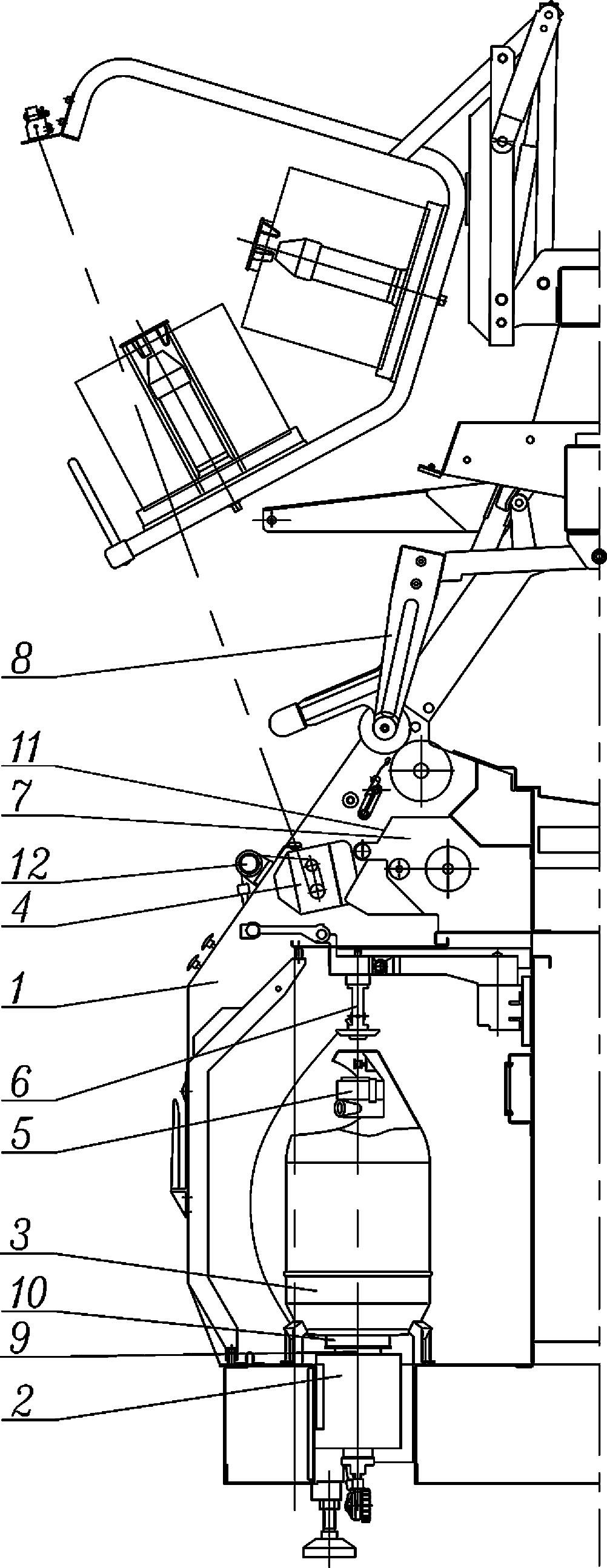
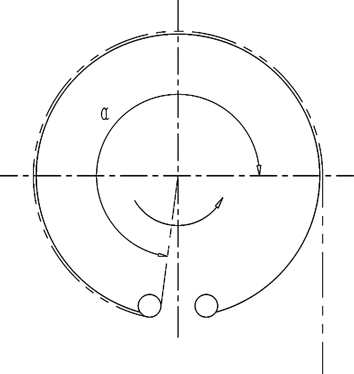
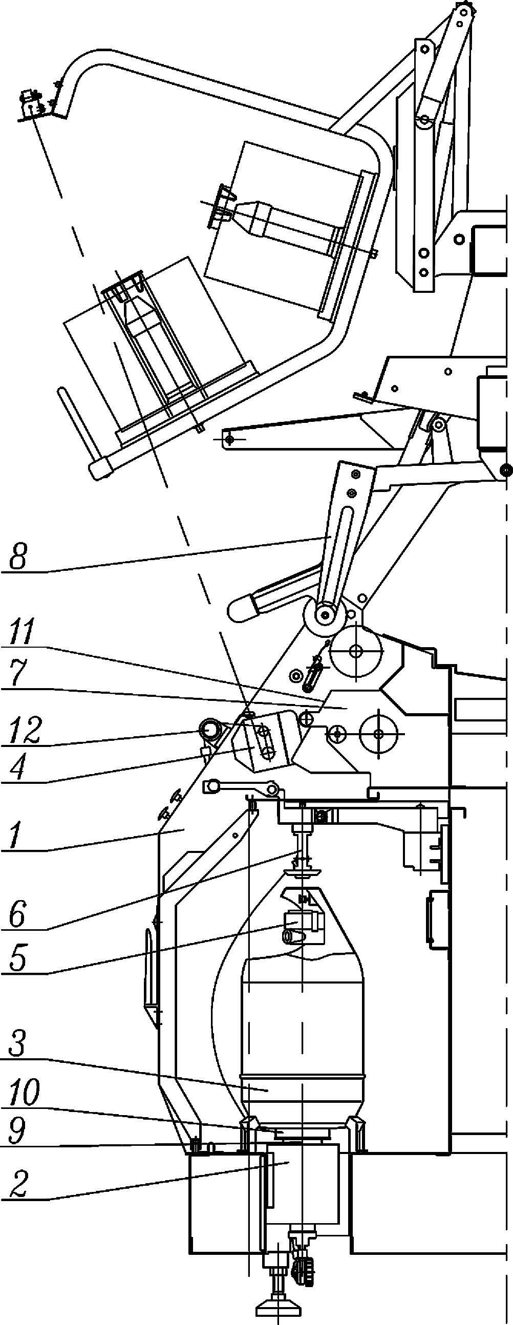

Image

  • Outer yarn tension regulating method for direct twisting machine
  • Outer yarn tension regulating method for direct twisting machine
  • Outer yarn tension regulating method for direct twisting machine

Examples


specific Embodiment 1

[0015] Specific embodiment one, such as figure 1 As shown, the outer yarn sequentially passes through the outer yarn tensioner 4, the spindle 3, and the yarn storage disc 10 located on the spindle 3, and merges with the inner yarn at the twist leveler 6. The steps for adjusting the tension of the outer yarn are as follows: A. Driven by the motor 2 The spindle 3 makes the outer yarn rotate to form a balloon; B. After the balloon is formed, use the control device 11 to adjust the tension through the outer yarn tensioner 4, so that the outer yarn surrounds the wrapping angle α of the yarn storage disc 10 Gradually reduce to 0 degrees, so as to achieve the effect of reducing the air circle.

specific Embodiment 2

[0016] Specific embodiment two, such as figure 1 As shown, on the basis of the first embodiment, an outer yarn tension detection sensor 12 is arranged between the outer yarn tensioner and the spindle, and the outer yarn tension detection sensor is used to detect the magnitude of the outer yarn tension. The control device 11 controls the outer yarn tensioner 4 according to the outer yarn tension value detected by the outer yarn tension detection sensor 12 to adjust the tension of the outer yarn so that the outer yarn wraps around the yarn storage disc. The angle α gradually decreases to 0 degrees, thereby achieving the effect of reducing the balloon.

[0017] In the above technical solution, under the same working conditions, the tension of the outer yarn is only changed by the outer yarn tensioner 4, and the shape of the balloon is adjusted to reduce the resistance of the air to the balloon, thereby reducing the energy consumption and the energy consumption of the equipment du...


PUM


Abstract

The invention relates to a method for fulfilling the aim of energy conservation by reducing a balloon in the operating state of the conventional direct twisting machine, in particular to a method for regulating the tension of outer yarns by controlling an outer yarn tensioner, which comprises the following steps of: A, driving a spindle by a motor, so that the outer yarns rotate to form the balloon; and B, after the balloon is formed, regulating the tension of the outer yarns by utilizing a control device through the outer yarn tensioner, so that a wrapping angle alpha of wrapping a yarn storage disc by the outer yarns is reduced to 0 degree gradually to achieve the effect of reducing the balloon. According to the technical scheme, the direct twisting machine also comprises an outer yarn tension detection sensor for controlling the tension of the outer yarns in real time. Therefore, by the outer yarn tension regulating method, the noise of equipment is reduced, power consumption is reduced, and the effect of energy conservation is achieved.

Description

technical field [0001] The invention relates to a method for adjusting the outer yarn tension of a direct twisting machine, which belongs to the technical application field of textile machinery. Background technique [0002] Existing direct twisting machine comprises a frame and motor, spindle, outer yarn tensioner, inner yarn tensioner, leveling device, overfeeding device and take-up device installed on the frame respectively, and motor is used for driving The spindle makes the outer yarn rotate to form an air circle. The spindle includes spindle rods, yarn storage discs and other components. The outer yarn passes through the outer yarn tensioner and the spindle into the twist leveler in turn. In the prior art, after the outer yarn rotates with the spindle to form a balloon, the tension is adjusted so that the outer yarn forms a wrapping angle α on the yarn storage disk between 270°-360° to maintain a stable balloon shape, but this state Under this condition, the equipment...

Claims


Application Information

Patent Timeline
IPC IPC(8): D01H13/10D01H13/32
Inventor 杨华明陆国兴潘松杨华年任晓军张金鹏许金甲
Owner YICHANG JINGWEI TEXTILE MACHINERY
Learn More