Lamp structure

A technology for lamps and lamp panels, applied in lighting devices, cooling/heating devices of lighting devices, light sources, etc., can solve the problems of wire falling off, not easy to fix, and LED lamps cannot operate normally, so as to avoid short circuit and simplify assembly The effect of the process

Inactive Publication Date: 2011-10-12
EVERLIGHT ELECTRONICS
View PDF5 Cites 12 Cited by
  • Summary
  • Abstract
  • Description
  • Claims
  • Application Information

AI Technical Summary

Problems solved by technology

On the other hand, because the multiple wires connecting the multiple LEDs inside the lamp and the external power supply are only connected to the LEDs by soldering through solder joints, the assembly process is complicated and not easy to secure. Therefore, when the wires are pulled by the outside, It is easy to cause the wire to fall off from the solder joint due to insufficient bonding force of the solder joint, resulting in the malfunction of the LED lamp

Method used


Image

  • Lamp structure
  • Lamp structure
  • Lamp structure

Examples


Embodiment Construction

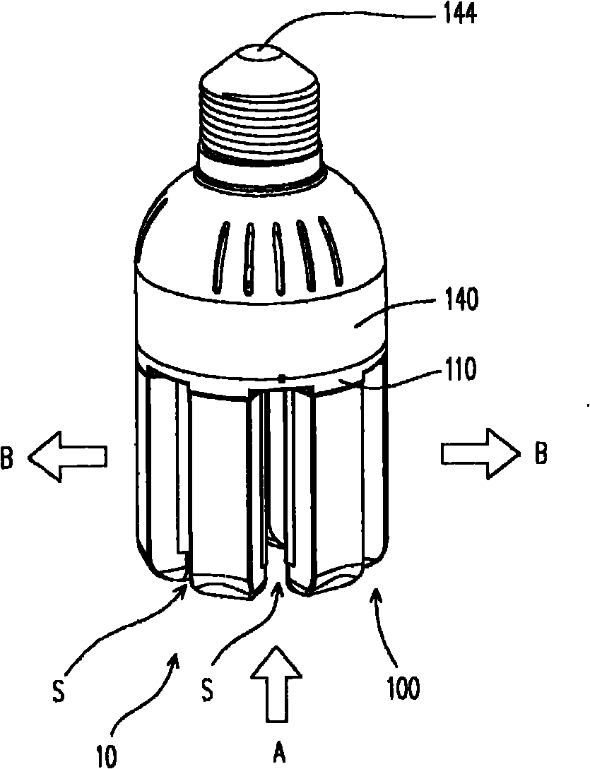
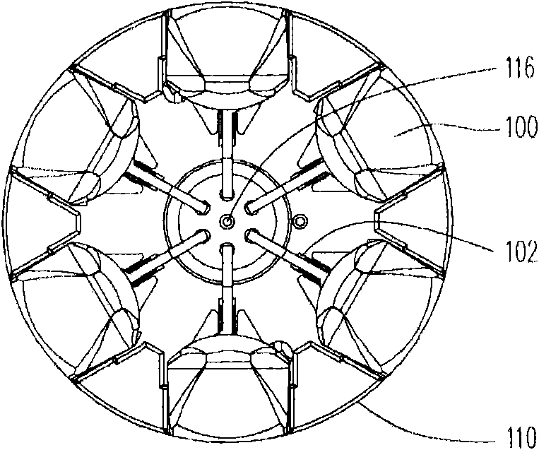
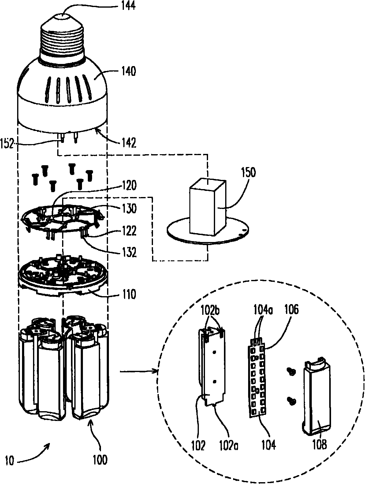
[0025] figure 1 It is an assembly diagram of a lamp structure according to an embodiment of the present invention. figure 2 It is a front view of the light emitting unit of the lamp structure according to an embodiment of the present invention. image 3 It is an exploded schematic diagram of the structure of a lamp according to an embodiment of the present invention.

[0026] Please refer to figure 1 , figure 2 and image 3 , the lamp structure 10 of the present invention is a lamp structure with lateral light output, wherein a plurality of light emitting units 100 are fixed on an insulating base 110 . Such as figure 2 As shown, the number of light-emitting units 100 is, for example, 6 or more, and each light-emitting unit 100 can be independently snapped on different directions of the insulating base 110 and emit light in different directions. Also because these light-emitting units 100 are arranged around the center of the insulating base 110, and a plurality of hea...


PUM


Abstract

The invention provides a lamp structure. The lamp structure comprises a lamp seat, an insulation base, a first electrode plate, a second electrode plate and a plurality of light emitting units, wherein the insulation base is provided with an annular groove and a radial groove positioned in the annular groove; a plurality of first through holes are formed at one end, away from the center of the insulation base, of the radial groove, and a plurality of second through holes are correspondingly formed at positions, adjacent to the first through holes, of the annular groove; the first electrode plate is arranged in the radial groove; a plurality of first terminals passing through the first through holes are arranged on the first electrode plate; the second electrode plate is arranged in the annular groove; a plurality of second terminals passing through the second through holes are arranged on the second electrode plate; and the plurality of light emitting units encircle the center of the insulation base and emit light from the side direction of the insulation base.

Description

technical field [0001] The present invention relates to a lamp structure, and in particular to a lamp structure with lateral light output. Background technique [0002] With the advancement of semiconductor technology, light emitting diode (LED) components can emit high-brightness light, and have the advantages of power saving, small size, low voltage drive, etc., so light emitting diode components have been widely used in various lighting in the device. [0003] Generally speaking, when a light emitting diode emits high-brightness light, a large amount of heat energy is generated. If the heat energy cannot be dissipated and continuously accumulated in the LED, the temperature of the LED will continue to rise. As a result, the light emitting diode may cause brightness attenuation and shorten service life due to overheating, and even cause permanent damage in severe cases. Therefore, today's lighting equipment using LEDs will be equipped with heat sinks to dissipate heat f...

Claims


Application Information

Patent Timeline
IPC IPC(8): F21S2/00F21V29/00F21V23/00F21K9/20F21V29/83
Inventor 许丰庭陈奕宏
Owner EVERLIGHT ELECTRONICS
Why Eureka
Try Eureka