Low-temperature air supply device

An air supply device and low-temperature technology, which is applied in the field of central air-conditioning low-temperature air supply device, can solve the problems of affecting the appearance, affecting the normal use of the room, wasting energy consumption of the air conditioner, etc., and achieve the effect of saving invalid energy consumption and solving the problem of condensed water

Inactive Publication Date: 2011-10-12
BEIJING SHUIMU ZEQING ENERGY TECH
View PDF6 Cites 6 Cited by
  • Summary
  • Abstract
  • Description
  • Claims
  • Application Information

AI Technical Summary

Problems solved by technology

[0003] 1. The air temperature and moisture content in the room are higher than the low-temperature air or fresh air mentioned above, and the air is directly supplied from the air outlet, and there is a backflow mixing area around the air outlet frame plate, and the air temperature and humidity content in this mixing area are high Because of the low-temperature air or fresh air sent, condensed water will be generated on the lower-temperature air supply frame plate, which will not only affect the appearance, but also affect the normal use of the room
[0004] 2. Whether it is the low-temperature air supply of ice-storage central air-conditioning or the low-temperature fresh air of central air-conditioning with separate temperature and humidity control, the air volume sent to the room needs to be adjusted according to the actual demand of the room’s cooling load and humidity load. In the air supply mode, due to the high wind speed in the air duct, the adjustment of the air volume in each room in the air system is poor, and the mutual interference is large. Therefore, the air supply in each room is often uneven, which not only affects the comfort of the air-conditioned room, but also wastes the energy consumption of the air-conditioning

Method used


Image

  • Low-temperature air supply device
  • Low-temperature air supply device
  • Low-temperature air supply device

Examples


Embodiment Construction

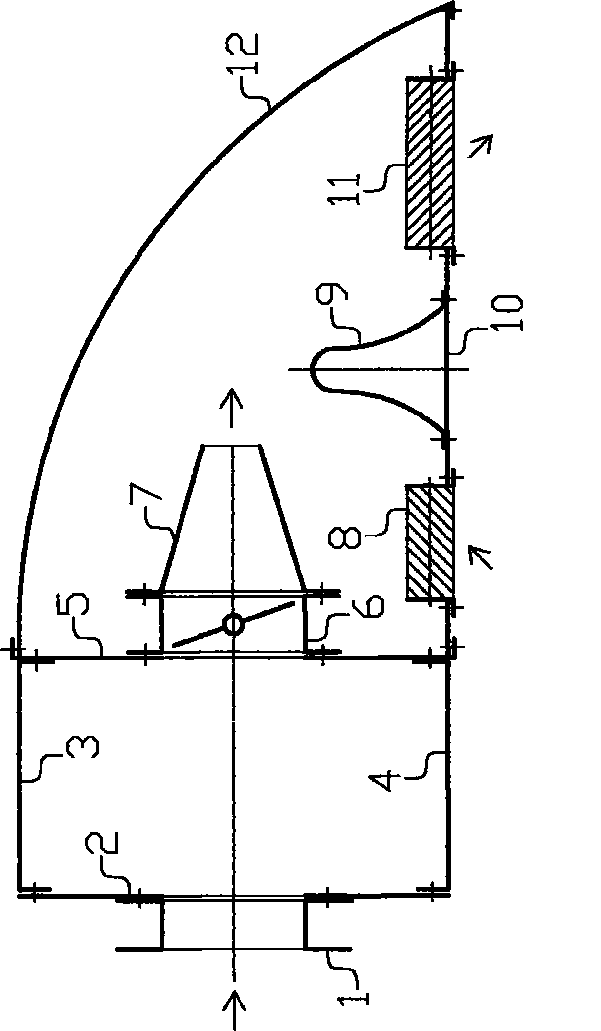
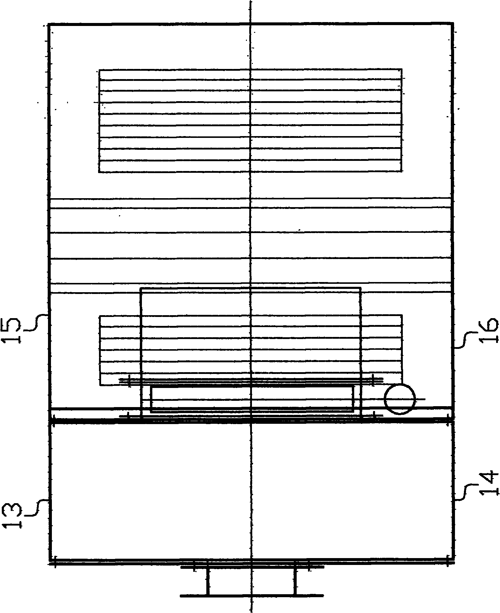
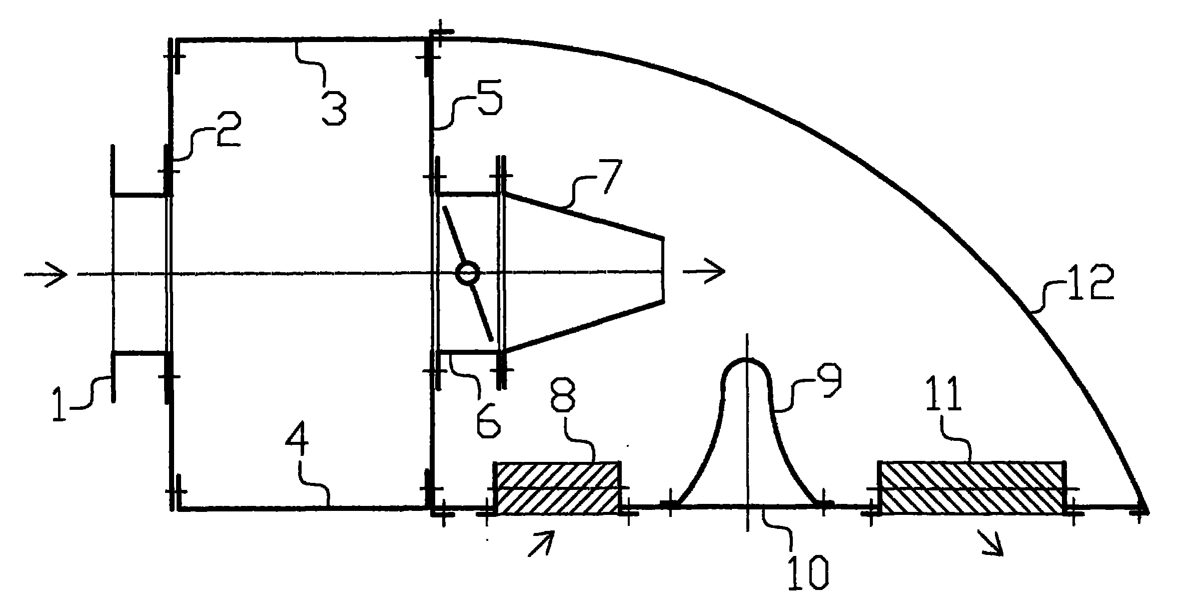
[0017] Refer to attached figure 1 , 2 , a low-temperature air supply device of the present invention includes the structural part of the air inlet pressure equalization box, the structural part of the adjustable induced air supply box and the built-in insulation layer. The above two parts are connected by folding plates through the neutral partition plate 5 to form the whole of the present invention. device. The structural part of the air inlet and pressure equalization box includes a short flange air inlet pipe 1 and a side vertical cabinet board 2, an upper cabinet board 3, a lower cabinet board 4, a front cabinet board 14, and a rear cabinet board. 13 and the neutral partition plate 5 are connected to each other through folded plates to form a pressure equalizing box, and the flange at one end of the flange air inlet short pipe 1 is connected with the opening periphery of the side vertical box body plate 2 to form the air inlet of the present invention. The structural par...


PUM


Abstract

The invention relates to a low-temperature air supply device which comprises an inlet air pressure equalizing box structure part, an air supply adjusting and inducing box structure part and a built-in heat-insulation layer, wherein the inlet air pressure equalizing box plays the roles of equalizing and stabilizing the pressure of an air supply pipe network of a central air conditioner and is convenient for adjustment of the air output for each room; the air supply adjusting and inducing box consists of an electric adjusting valve, a jet tapering air port, an air return port, an Omega-shaped backpressure plate, an air supply port and a box body plate; under the action of high-speed jet airflow, an air return negative pressure region and an air supply positive pressure region in the box are formed; air in each room is induced by the negative pressure to enter the box via the air return port and is mixed with the low-temperature air jet; and the mixed airflow enters the positive pressure air supply region after temperature rise and is fed to the room through the air supply port; and therefore, according to the low-temperature air supply device disclosed by the invention, the actual problems that the air output is adjusted as required in each room, condensed water is generated in the air supply port, and the like are solved.

Description

technical field [0001] The invention relates to a central air-conditioning low-temperature air supply device Background technique [0002] In the current central air-conditioning field, ice storage and temperature-humidity control central air-conditioning systems all involve low-temperature air or fresh air supply technology. The general practice is to pass low-temperature air or fresh air from the air duct through the ordinary air supply outlet in the room, such as Venetian air outlets, grille air outlets, diffusers, etc. are directly sent into the room. Theory and engineering practice show that the current air supply methods for low-temperature air or fresh air have the following defects: [0003] 1. The air temperature and moisture content in the room are higher than the low-temperature air or fresh air mentioned above, and the air is directly supplied from the air outlet, and there is a backflow mixing area around the air outlet frame plate, and the air temperature and h...

Claims


Application Information

Patent Timeline
Patent Type & Authority Applications(China)
IPC IPC(8): F24F13/04F24F13/22F24F13/08F24F11/02
Inventor 谢峤甄华斌
Owner BEIJING SHUIMU ZEQING ENERGY TECH
Why Eureka
Try Eureka