Sensing head of omni-directional wind speed sensor
A technology of sensitive head and sensor, used in the direction of measuring fluid velocity using thermal variables, to achieve the effect of long service life, easy maintenance and little disturbance
- Summary
- Abstract
- Description
- Claims
- Application Information
AI Technical Summary
Problems solved by technology
Method used
Image

Examples
Embodiment 1
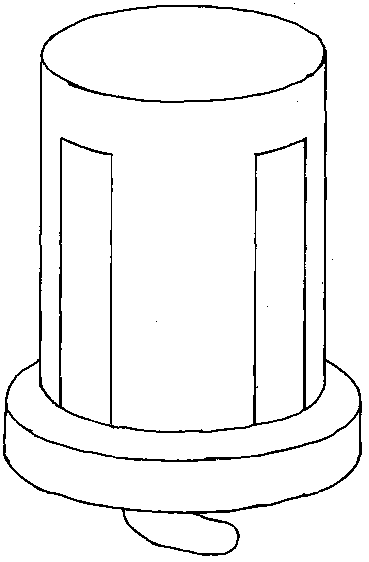
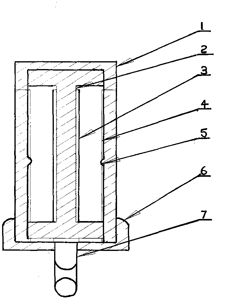
[0031] The full wind direction wind speed sensor sensitive head of the present embodiment, such as Figure 1-2 As shown, it includes sensitive head housing 1, heating element support 2, heating element 3, heat conductor 4, temperature sensor 5, base 6 and cable 7; heating element support 2 and heating element 3 are located in sensitive head housing 1, and generate heat The element 3 is located on the heating element support 2; the temperature sensor 5 is located on the heat conductor 4, the sensitive head housing 1 is provided with a slot, and the end surface of the sensitive head housing 1 is provided with an installation groove in the slot, and the heat conductor 4 is located in the installation groove Inside; the sensitive head shell 1 is installed on the base 6, and the cable 7 installation hole is opened in the axial direction of the sensitive head shell 1 and the bottom of the base 6. The slot is located at a position of 0° parallel to the axial direction of the sensitiv...
Embodiment 2
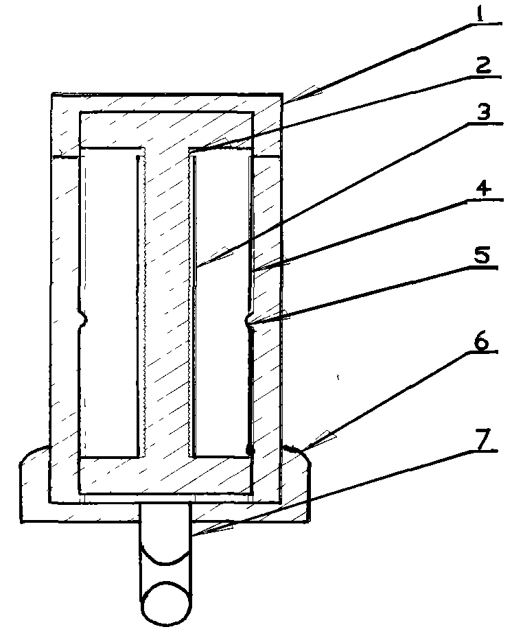
[0034] The full wind direction wind speed sensor sensitive head of the present embodiment, such as figure 1 As shown in -3, it includes sensitive head housing 1, heating element support 2, heating element 3, heat conductor 4, temperature sensor 5, base 6 and cable 7; heating element support 2 and heating element 3 are located in sensitive head housing 1 , the heating element 3 is located on the heating element support 2; the temperature sensor 5 is located on the heat conductor 4, a slot is provided on the sensitive head housing 1, and an installation groove is provided on the end surface of the sensitive head housing 1 in the slot, and the heat conductor 4 is located on In the installation groove; the sensitive head housing 1 is installed on the base 6, and the cable 7 installation hole is opened in the axial direction of the sensitive head housing 1 and the bottom of the base 6. The slot is located at a 90° position parallel to the axial direction of the sensitive head housi...
Embodiment 3
[0036] The sensitive head of the full wind direction, wind speed and direction sensor of the present embodiment, such as Figure 1-2 As shown, it includes sensitive head housing 1, heating element support 2, heating element 3, heat conductor 4, temperature sensor 5, base 6 and cable 7; heating element support 2 and heating element 3 are located in sensitive head housing 1, and generate heat The element 3 is located on the heating element support 2; the temperature sensor 5 is located on the heat conductor 4, the sensitive head housing 1 is provided with a slot, and the end surface of the sensitive head housing 1 is provided with an installation groove in the slot, and the heat conductor 4 is located in the installation groove Inside; the sensitive head shell 1 is installed on the base 6, and the cable 7 installation hole is opened in the axial direction of the sensitive head shell 1 and the bottom of the base 6. The slot is located at a position 270° parallel to the axial dire...
PUM
 Abstract
Description
Claims
Application Information
 - R&D
- Intellectual Property
- Life Sciences
- Materials
- Tech Scout
- Unparalleled Data Quality
- Higher Quality Content
- 60% Fewer Hallucinations
Browse by: Latest US Patents, China's latest patents, Technical Efficacy Thesaurus, Application Domain, Technology Topic, Popular Technical Reports.
© 2025 PatSnap. All rights reserved.Legal|Privacy policy|Modern Slavery Act Transparency Statement|Sitemap|About US| Contact US: help@patsnap.com