Electronic equipment and input method thereof

An electronic device and input method technology, applied in the electronic field, can solve problems such as increased signal-to-noise ratio, complex algorithm processing, and insufficient robustness of results, etc., to achieve the effects of expanding the application range, eliminating false recognition phenomena, and improving anti-light interference performance

Active Publication Date: 2013-09-04
LENOVO (BEIJING) LTD
View PDF3 Cites 0 Cited by
  • Summary
  • Abstract
  • Description
  • Claims
  • Application Information

AI Technical Summary

Problems solved by technology

[0007] The disadvantage of this scheme is: limited by the power of the active light source, the increase of the signal-to-noise ratio has a certain limit
The disadvantage of this scheme is: the algorithm processing is complicated, and the result is not robust enough

Method used


Image

  • Electronic equipment and input method thereof
  • Electronic equipment and input method thereof
  • Electronic equipment and input method thereof

Examples


Embodiment Construction

[0047] The specific implementation manners of the present invention will be described in detail below with reference to the accompanying drawings.

[0048] Embodiments of the present invention are specifically described below. First introduce the principle of retroreflection.

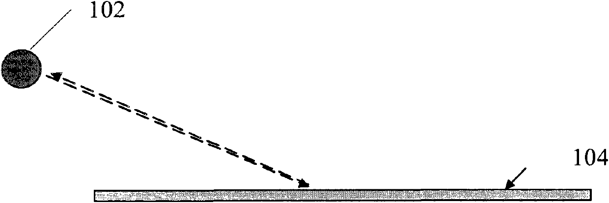
[0049] figure 1 is a schematic diagram of the principle of retroreflection;

[0050] 102 in the figure is a light source, and the emitted light is incident on the retroreflective surface 104, and the retroreflective surface 104 basically returns the incident light along the original path.

[0051] Retroreflection, also known as retroreflection or retroreflection, is very different from our common diffuse reflection and specular reflection. Diffuse reflection is the reflection of reflected light in all directions and is isotropic. The angle of reflection and the angle of incidence of a specular reflection are the same, but the reflected ray and the incident ray are on either side of the normal to the...


PUM


Abstract

The invention provides electronic equipment. The electronic equipment has a physical surface and comprises a retroreflection component, an image acquisition unit and a processing unit, wherein the retroreflection component is arranged on the first rim of the physical surface and used for retroreflecting a first optical effect produced by a first light source; the image acquisition unit is arranged on the second rim, opposite to the first rim, of the physical surface; an acquisition region of the image acquisition unit faces the retroreflection component and is used for acquiring an image of asecond optical effect; the second optical effect is formed on the first optical effect after an operating body enters a touch region; the touch region is an overlapped region of an irradiation regionof the first light source and an acquisition region of the image acquisition unit; and the processing unit is connected with the image acquisition unit and used for determining a corresponding position of the operating body in the image of the second optical effect to determine a position range of the operating body in the touch region. The invention also provides an input method. By the technical scheme of the invention, the light interference resistance of an optical touch screen in the electronic equipment is enhanced and error recognition phenomena are reduced.

Description

technical field [0001] The invention relates to the field of electronics, in particular to an electronic device and an input method thereof. Background technique [0002] At present, optical touch technology has been widely used. For example, a light source is used to illuminate the screen area. When the operating body enters the illuminated area, the reflected light of the operating body is captured by the camera, and the position of the finger can be located according to the reflected light image. [0003] There is a known technical solution as follows: a retroreflective reflective strip is arranged at the frame of the touch screen, and an active light source is used to generate light toward the retroreflective reflective strip at the opposite frame of the touch screen, and the retroreflective reflective strip basically directs the light of the active light source to the original path Return, reflect to the vicinity of the active light source, and set up a camera near the ...

Claims


Application Information

Patent Timeline
Patent Type & Authority Patents(China)
IPC IPC(8): G06F1/16
Inventor 陈柯杨锦平张晓平王竹强
Owner LENOVO (BEIJING) LTD
Why Eureka
Try Eureka